As much as I love the ESP8266 programmable Wifi enabled microcontroller, it still has some annoying issues: they’re not breadboard friendly and require some special wiring to put them into flash mode. To solve these issues, I decided to make a dedicated ESP8266 flasher using a USB FTDI module and some perf board.
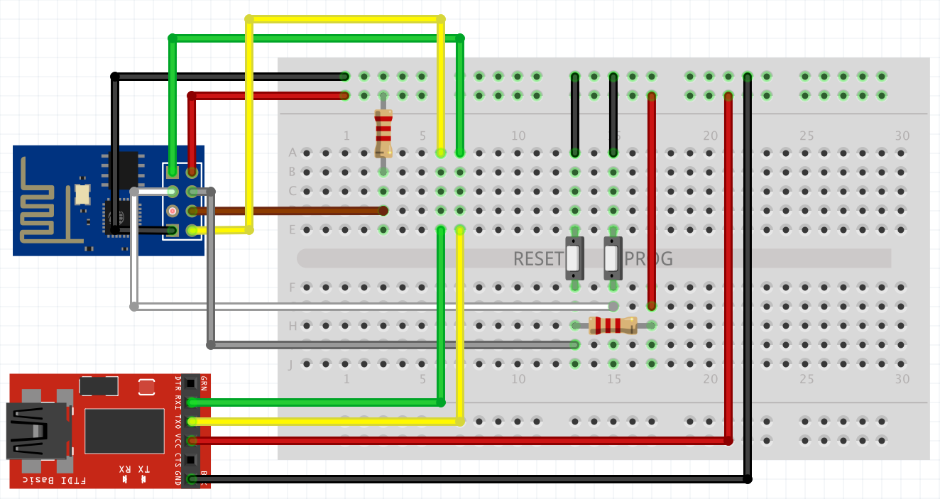
To put the ESP8266 in flash mode, GPIO_16 should be pulled low, while GPIO_0 is pulled low. Or, to describe it a bit more understandable using the diagram below: The module must be reset while holding the prog button.
In addition to the two buttons, the CH_PD pin and reset pin both are connected to a 2k2 pull up resistor.
Since the ESP8266 is a 3v3 unit, I use a 3v3 FTDI module. This save my from going to the trouble of level shifting.
With everything working fine on my breadboard, let’s start working on a PCB version using some perf board …
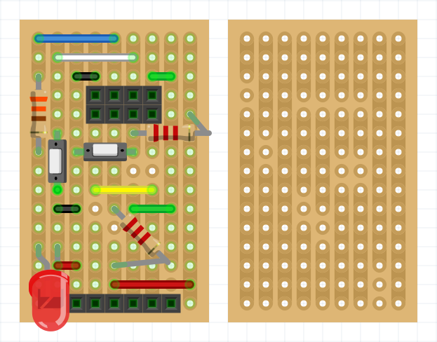
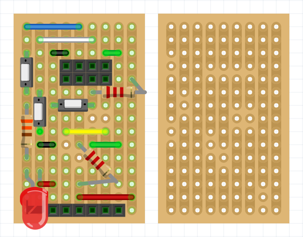
As you can see in the drawing above, I added a LED and 330ohm resistor on GPIO_2 so I can use this GPIO pin during debugging. Honestly, I didn’t test this out on my bread bord, but hey, what could go wrong?

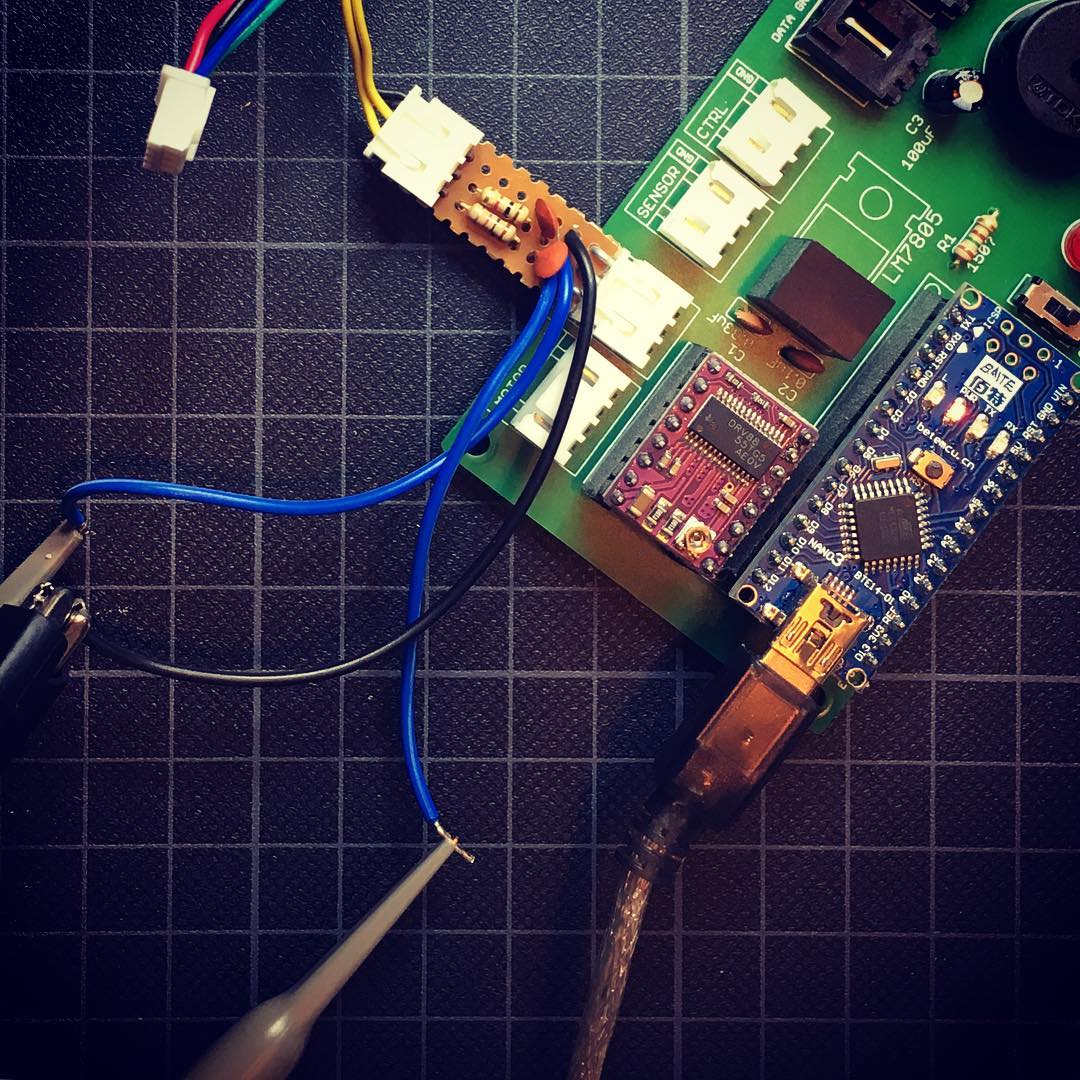
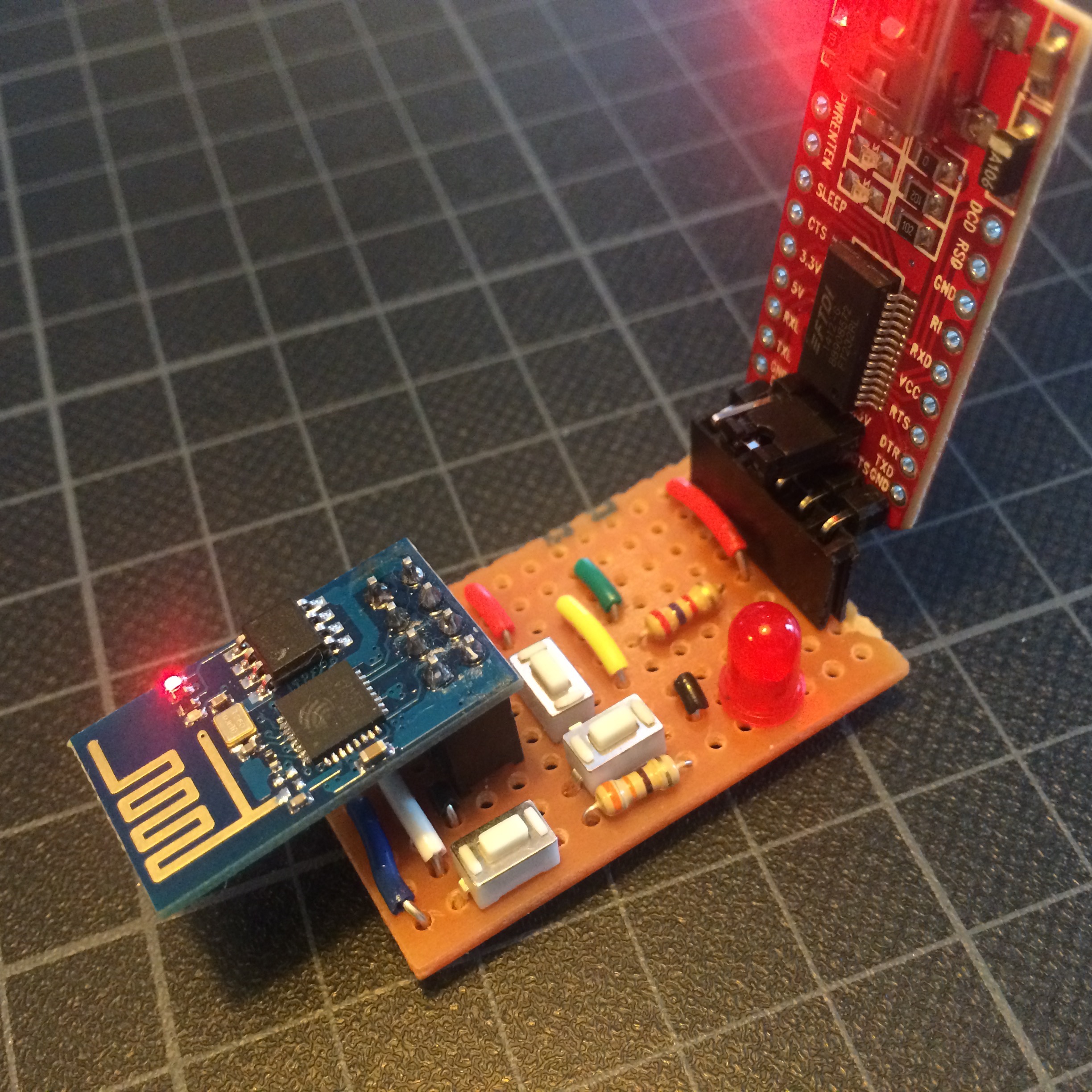
After working out my wiring using Fritzing, I pulled some materials out of my drawer and created this fine peace of colorful art.
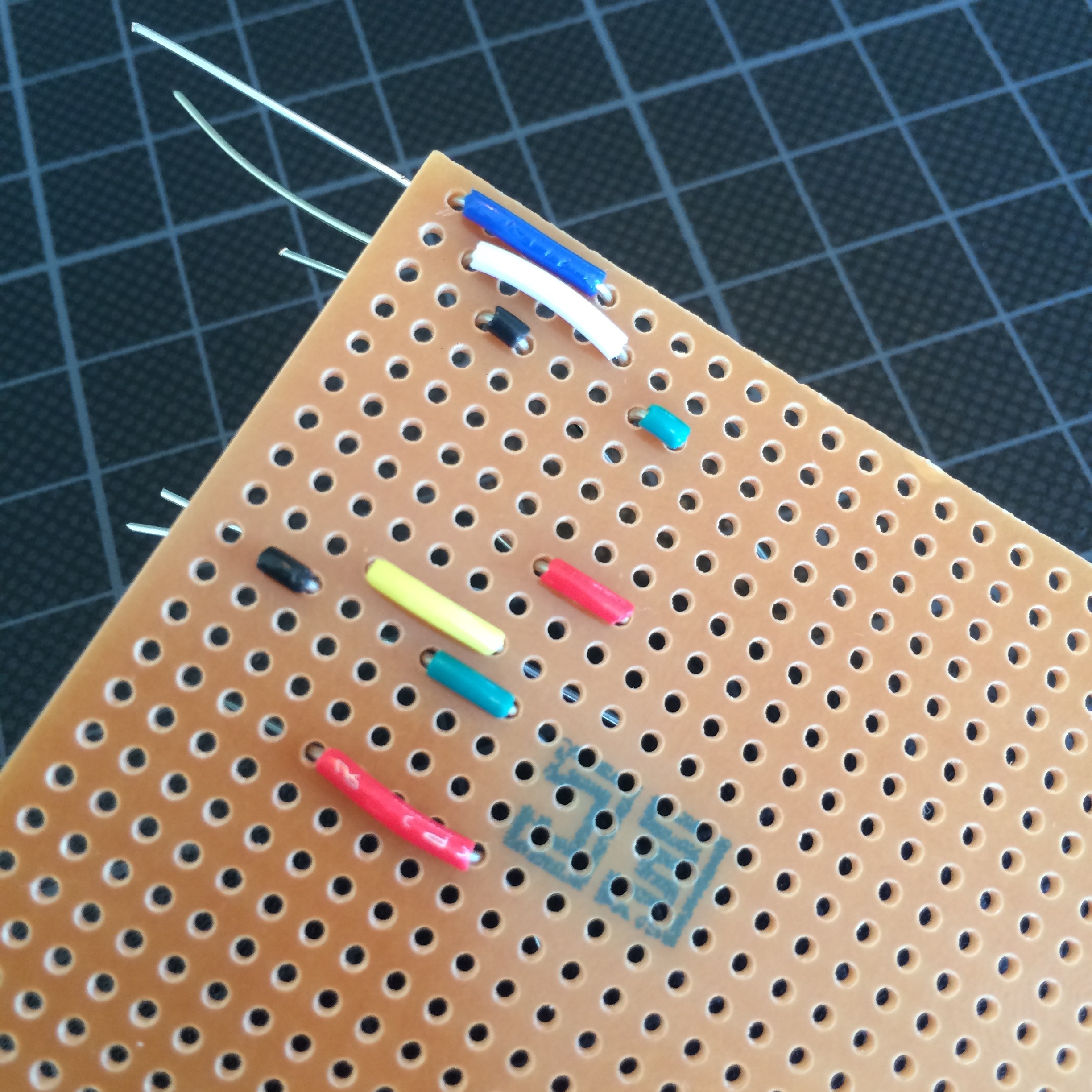
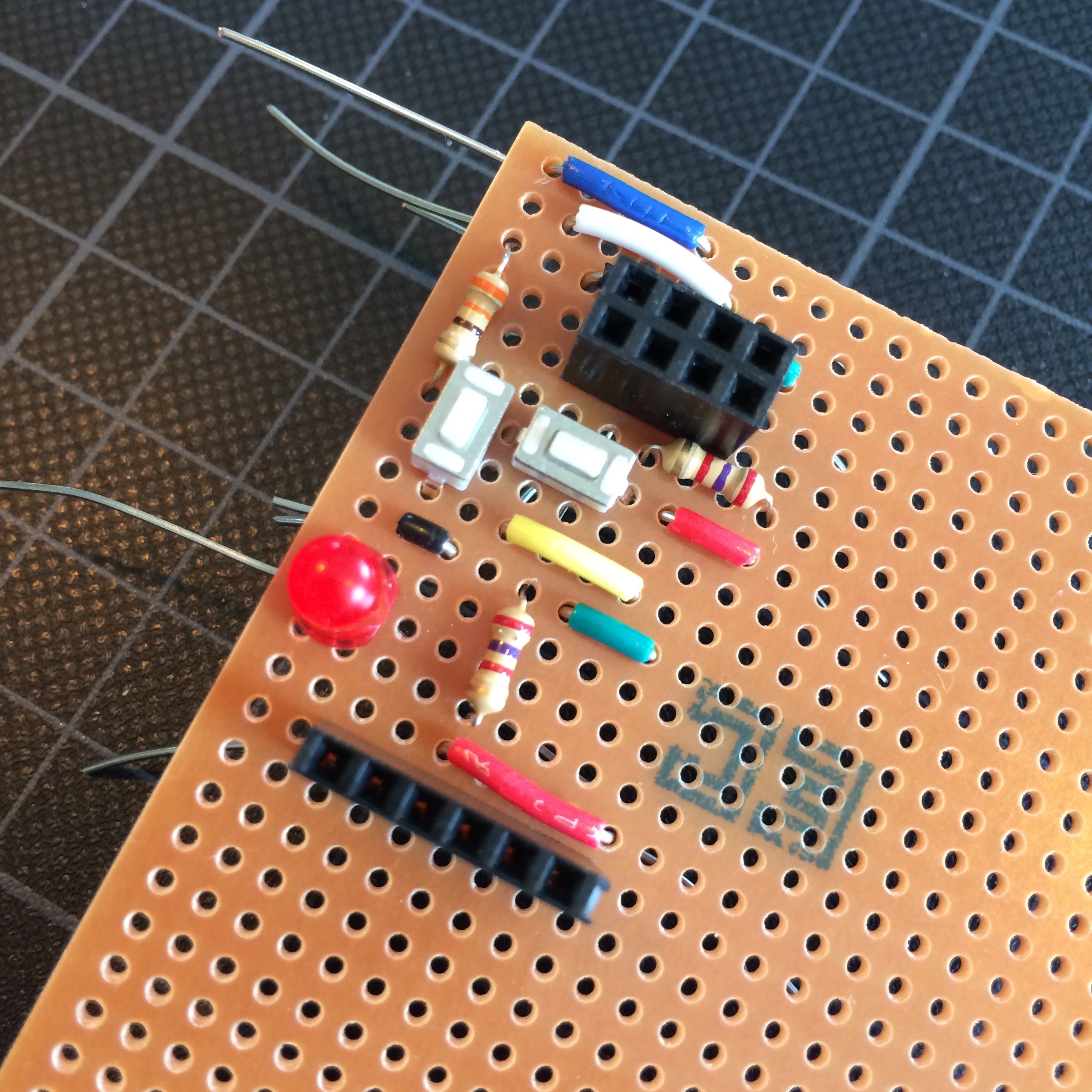
With the wires in place, I added the other components to finish up to top side of my master piece.
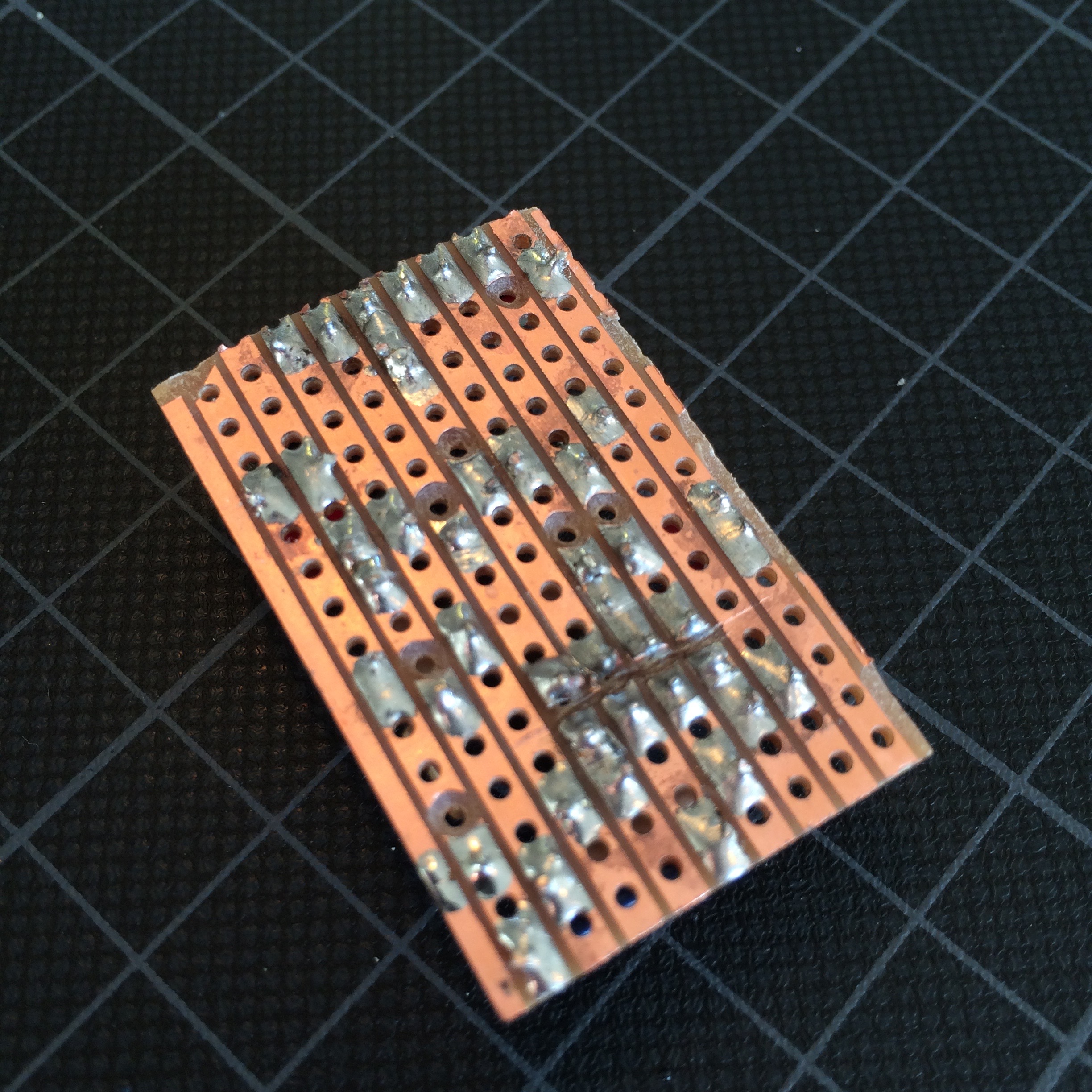
Now it’s time for the fun part: the soldering. Usually I solder every piece directly after adding them to the perf board. But every once in a while I feel like a rebel and take the anarchy route!
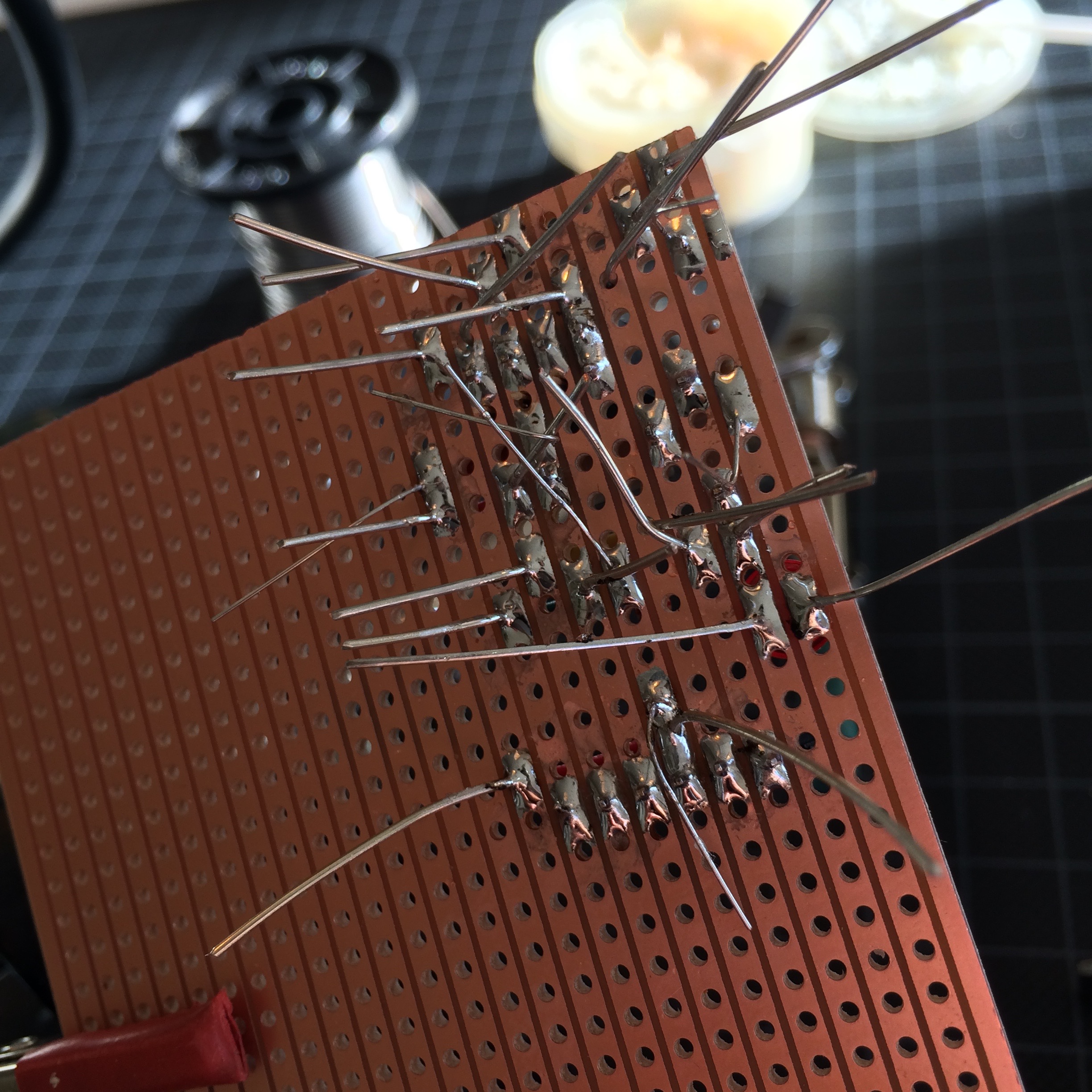
Now it’s time to cut some of the perf board connections. The reason I cut the connection on both sides of a hole in the perf board drawing, is because I like to use a drill bit for this. This works like a charm and can easily be done by hand.
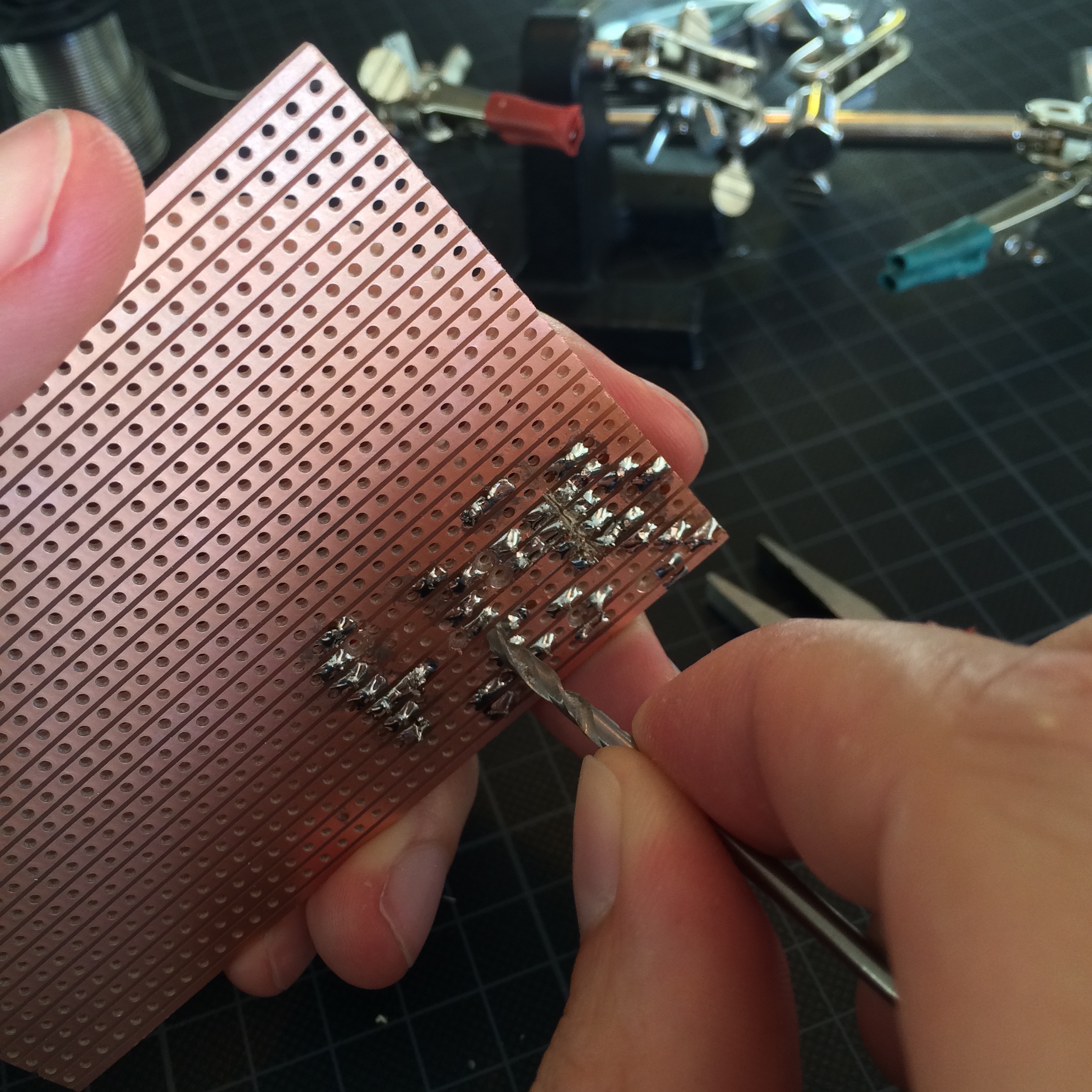
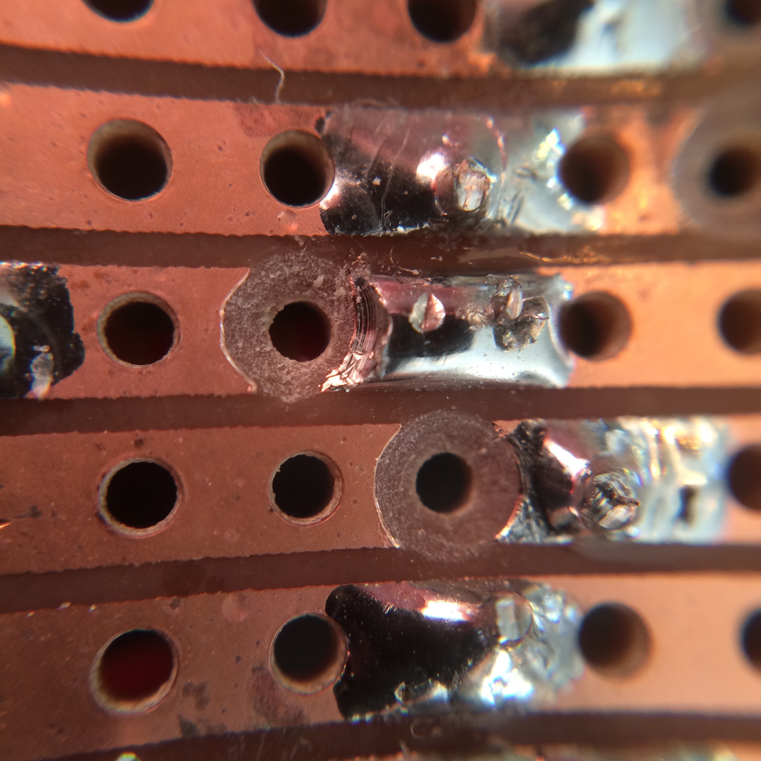
The result is a perfect and clean disconnected perf board strip.
Unfortunately I can’t use this technique to disconnect the pads between below the ESP8266 headers. Is is done with a knife, brute force and some minor cussing.
With everything in place, it was time to go for a spin. Unfortunately the board wasn’t able to flash the ESP8266. A cryptic error message told me I did something wrong and i should start crying for help:
warning: espcomm_sync failed
error: espcomm_open failed
The only change I had made since my working breadboard version, was the led connected to GPIO_2. With this in mind, I disconnected these extra components and managed to get it working.
One extra button solved the issue and allowed me to use the debug LED whenever necessary. The new breadboard drawing now looked like this:
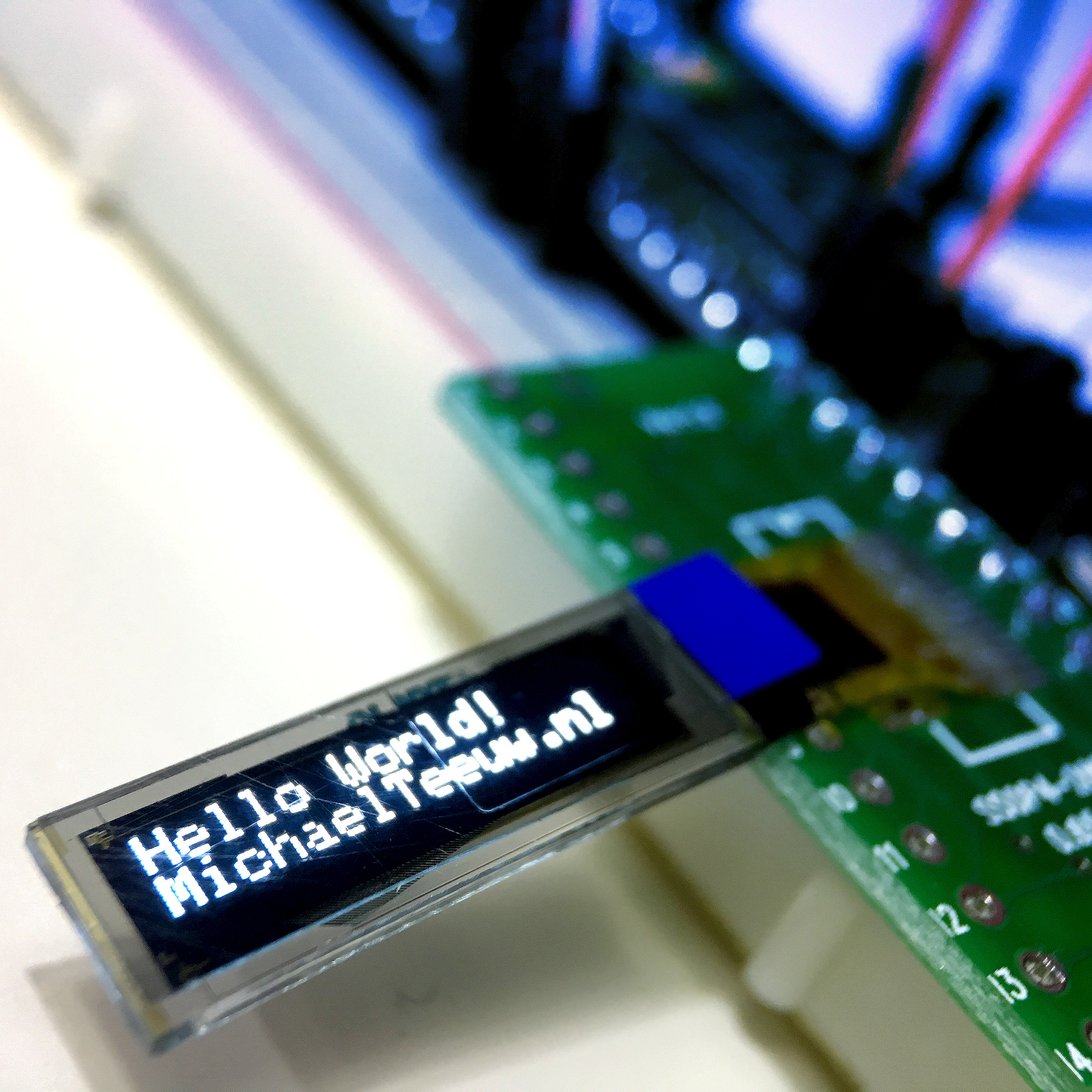
And with this modification, the ESP8266 flasher is done and ready for action!
Honestly, after building this, I must admit it isn’t the most user friendly setup. The buttons are placed in awkward positions and the board doesn’t allow be to connect any other peripherals.
So for the time being, it’s usable, but don’t be surprised if I work on a version 2 soon.
If you have any suggestions for version 2, let me know in the comments down below!