

A New Beginning
You're still there? Great! It has been almost 2 years since I've wrote my last blogpost. Time for an update. Not only in the form of a new post. Time for a full blog revamp! Time for a new makerspace! Time for a new beginning!

Quiet for now & plans for the future
If you are a regular reader of my blog, you know I’ve been posting new updates approximately every two weeks for the past few years. So the fact that my last post was over 6 weeks ago deserves a bit of an explanation.
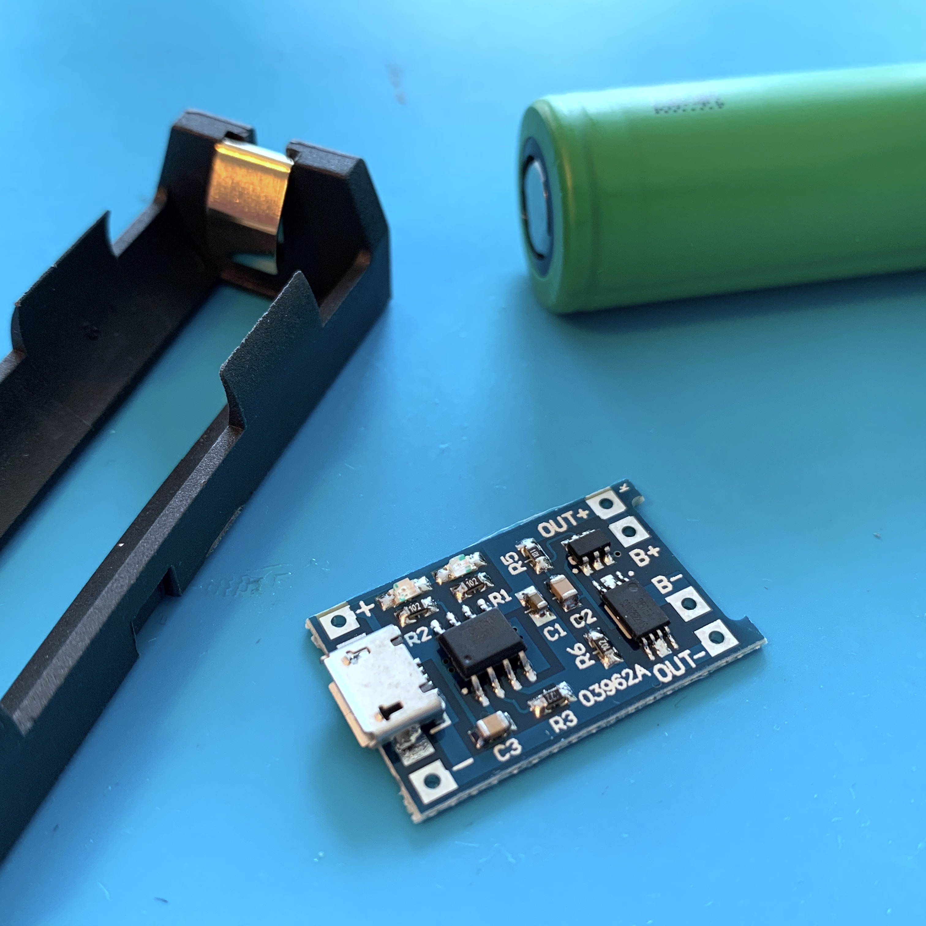
Solving a Hot and Sticky situation
In the past few weeks, life got a little bit in the way of my maker-hobby. To make sure I got my monthly doses of tinkering, I decided to take on a quick and fun one hour project this weekend: solving a hot and sticky situation.
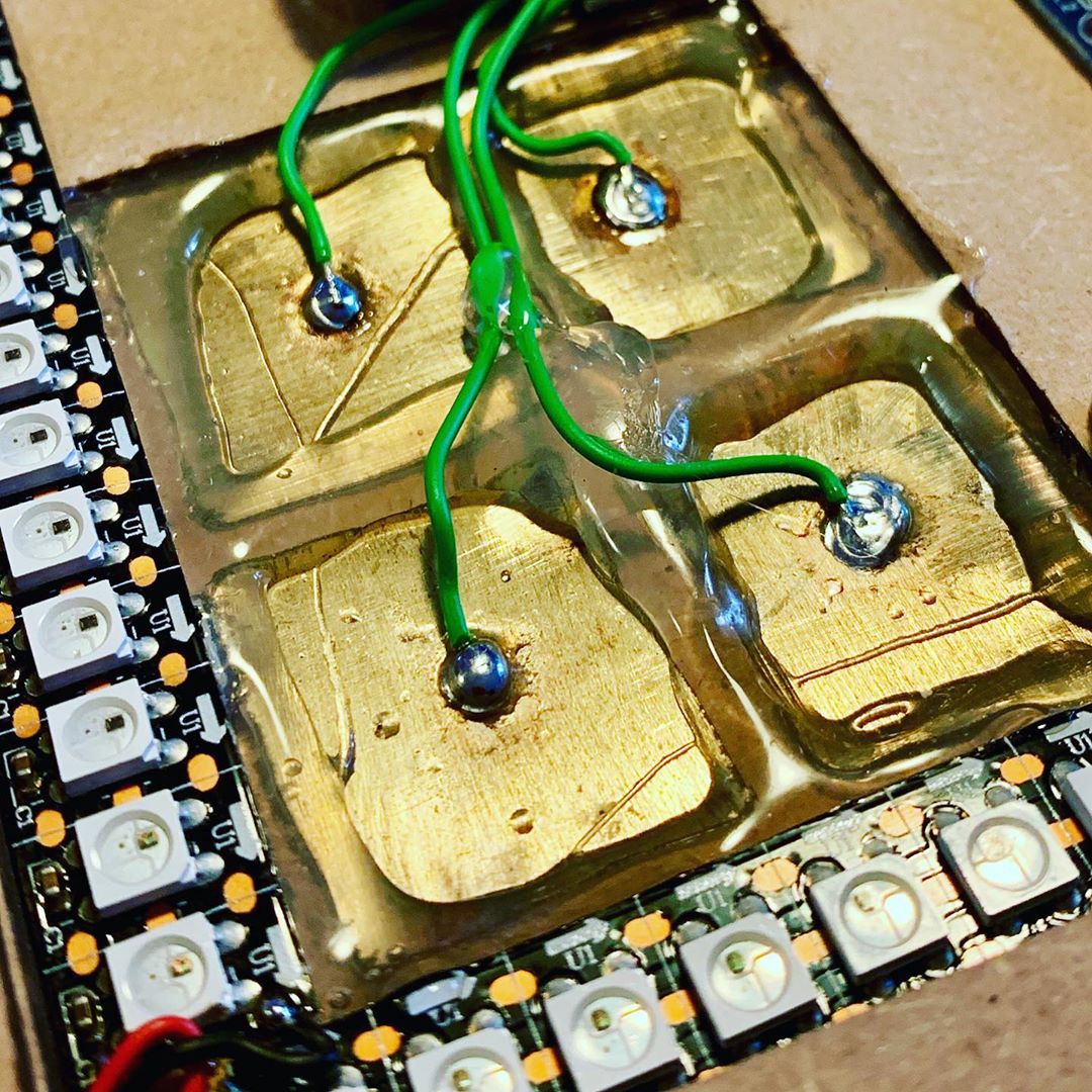
MusiCubes:
Touch Me Four Times
It’s been a few months since I’ve finished my MusiCubes Controller. And although most of the controller works perfect, there is one issue that is still bugging me: the false positives of the touch sensors. Time to fix this!
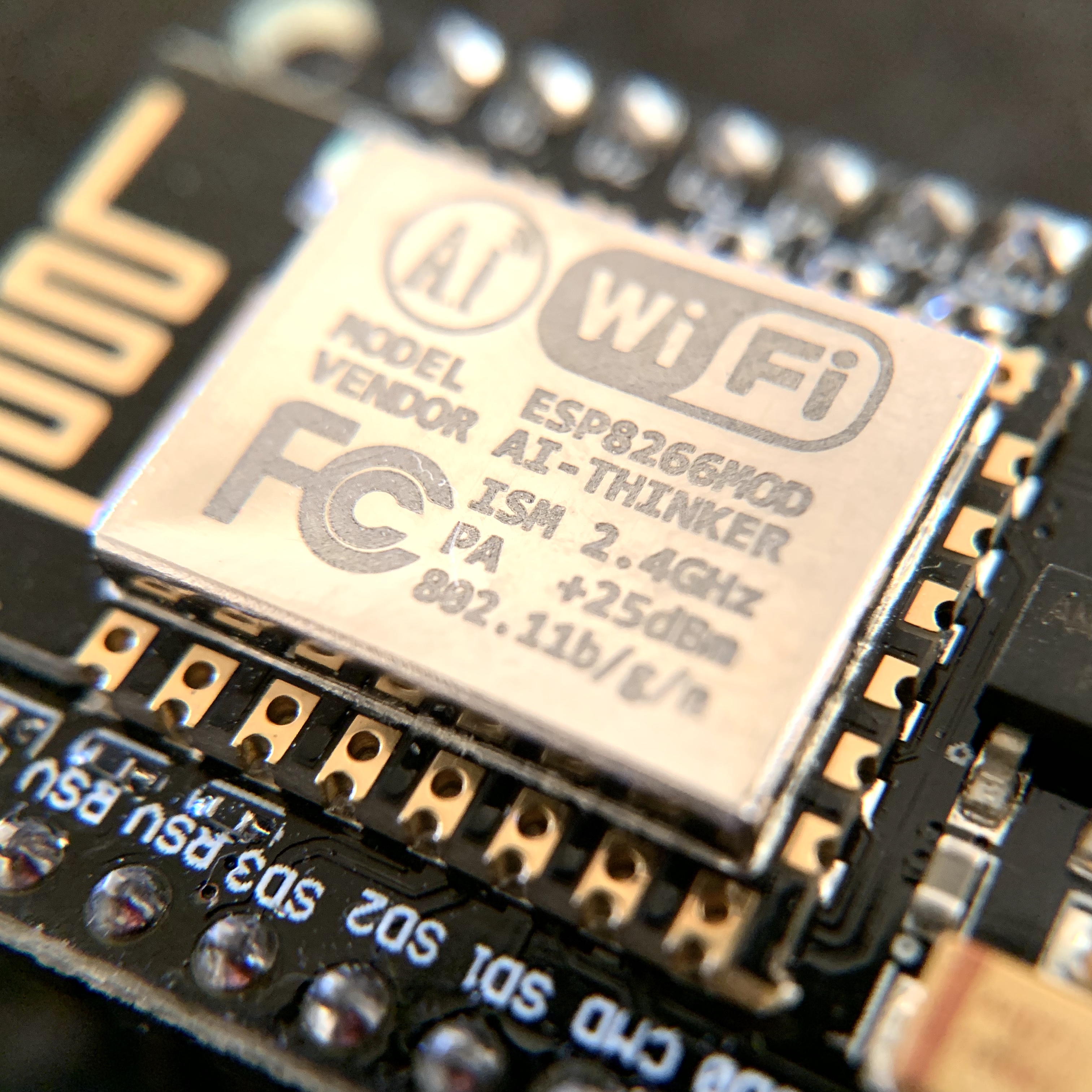
Connecting an ESP8266 to AWS IoT
During my day job I make a lot of use of Amazon Web Services. And because of this, I recently attended the AWS Summit in Amsterdam. Of course, a day like that can’t end without some tinkering …
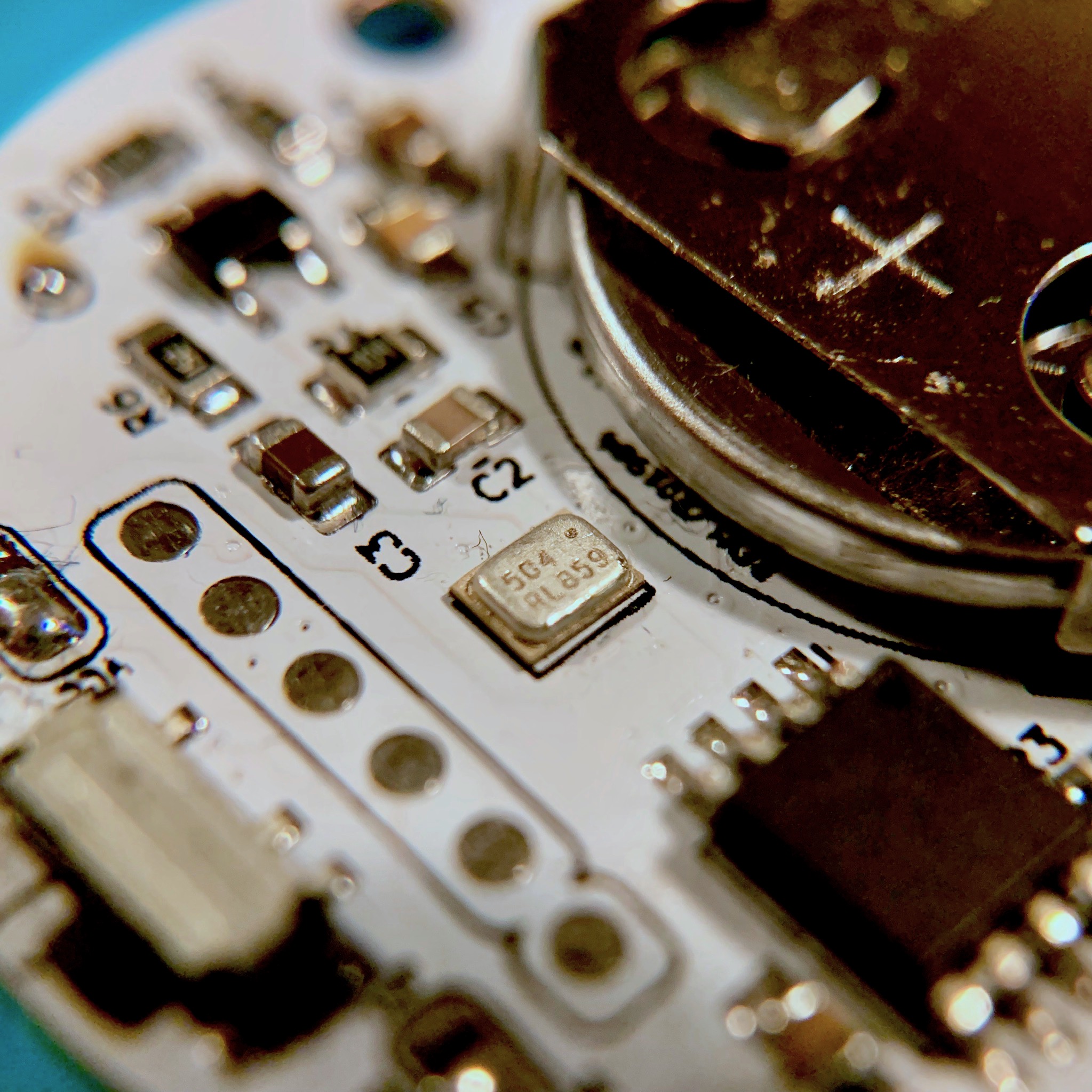
The Fire Proof Birthday Candle
This week we celebrated the first birthday of my youngest son, Luca. So it is time for him to blow out his first candle. Of course you can't trust a one-year-old to not set the house on fire when handling a candle, so we need to solve this with some electronics.
The Ridiculous Kitchen Timer™
I’m a huge coffee addict. As for many of us, coffee is the core ingredient for my projects. And since I like quality coffee we own a manually operated espresso machine. If the grind is perfect, and you use the ideal brewing time, the coffee will be able to fuel any project. But how to measure the perfect brewing time? The Ridiculous Kitchen Timer™ to the rescue!

A Place To Sleep
It’s been 10 months since my second son was born. And Since then, he has been sleeping in a crib in our master bed room. And as much as I love him, It was time for him to move out. Out of our bed room at least … Time to built him a place to sleep.

MusiCubes:
The Finishing Touch
Starting a project isn’t difficult. Finishing is. Or as they say: the last 20% is always the hardest part. But no worries, today we’ll finish this project by working on the final details.
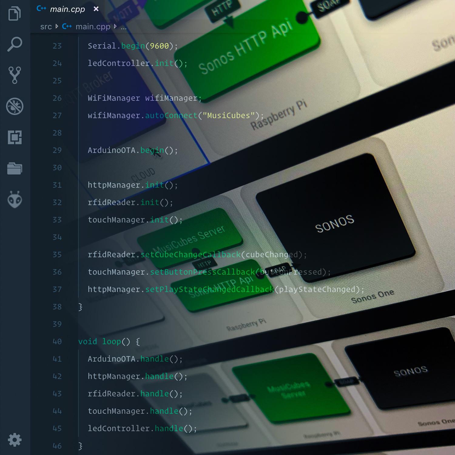
MusiCubes:
The Software
Two weeks ago I finished up the electronics of the MusiCubes controller. So now it’s time to discuss the software side of things. Buckle up, and get ready for the long ride!
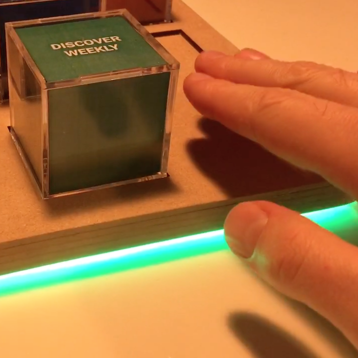
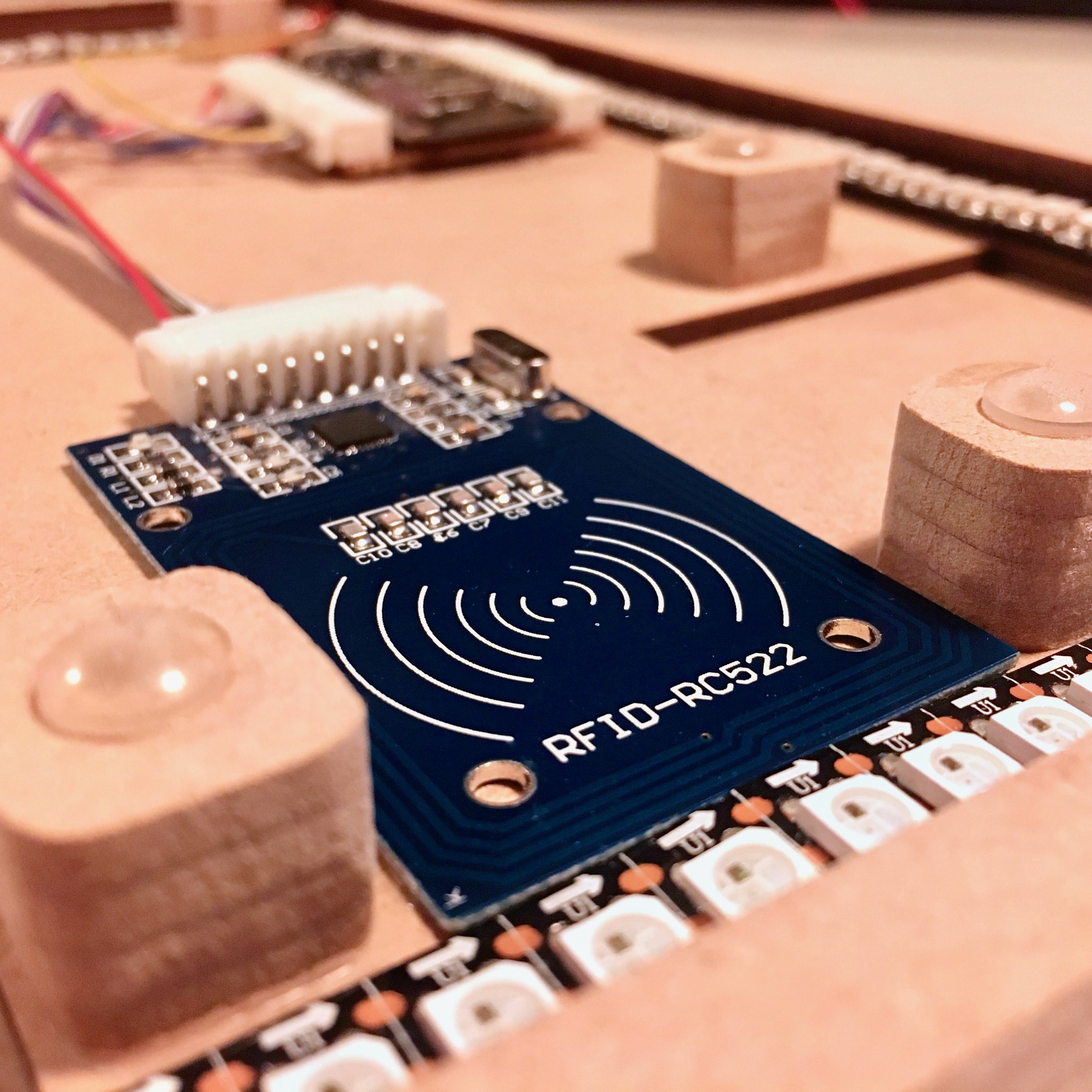
MusiCubes:
Touch Me!
Now that the MusiCubes tray is assembled and the RFID-sensor and LEDs are working as expected, It’s time to add the last feature of the original concept: invisible capacitive touch sensors to control the volume of the music.
MusiCubes:
Assembling The Tray
After last week’s proof of concept it is time to assemble the MusiCubes tray. Just slap on some wood glue and you’re ready to go! What could go wrong, right?
MusiCubes:
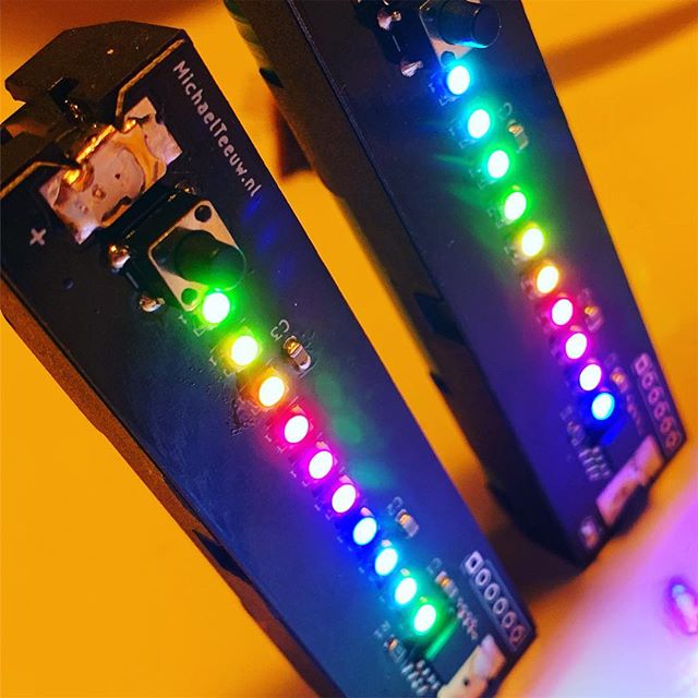
Concept & Prototyping
Most of my projects start behind my desk, Tinkering. But every now and then, new ideas come to mind while I’m not geeking. Just as with my MagicMirror, those projects and ideas are usually the best. Today I start a new project which, just as with my MagicMirror, popped in my mind far away from my soldering iron and computer: A digital music controller in an analog form factor.

What are you looking at?
2 weeks ago I strained my back while doing the heavy duty task of putting my 7 month old son to bed. As a lot of us desk nerds, my core muscles are non existent, so this was a matter of time for it to happen. Unfortunately it means I currently can’t spent any time behind my desk. Luckily there are other ways of fulfilling my maker needs.

Fixing Annoyances
When I bought my 3D printer a little over 3 years ago, I convinced my wife that it wasn’t just yet another useless gadget. I told her it was a tool which would help me solve problems I didn’t know I had. This week, I solved one of those problems using Fusion 360 and a few meters of white filament.

A Tiny Mistery: The Odd Leds
After the previous breakthrough which allows me to program the ATTiny10 and a small delay caused by a wonderful sunny Ibiza holiday, it’s time to get the WS2812 2020 leds working on this wonderful small microcontroller.

A Tiny Success: Flashing the USBasp
Two weeks ago I posted about my experiment with the ATTiny10. A 12Mhz 8-bit micro controller small enough to be confused with an obese ant. Unfortunately I didn’t succeed in programming this tiny guy, so this week I continue my small scale flashing quest.

A Tiny Failure
If you are a regular visitor of my blog, you might know that (with a few exceptions) I’ve been posting a new blog posts every two weeks. Unfortunately I skipped this regular update last week, because I’ve been a little bit sick. Nothing major, but I didn’t want to contaminate my boxes of SMD components with germs. So after a few days of sleep it’s time to get back to business and start with something small. Literally.

Designing my own Sonos Wall Mount.
A few weeks ago I bought two Sonos One speakers. Mounting them to the wall could be done using some purchased mounts. But when you own a 3D printer it’s more fun to design and print a mount yourself.
Train Automator:
Wrapping it up!
Over the course of the last few weeks I’ve been building the Arduino powered Model Train Automator. I’m sure my dad would like to start using it, so let’s wrap this project up!
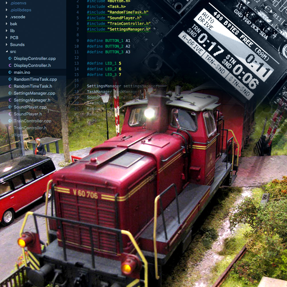
Train Automator:
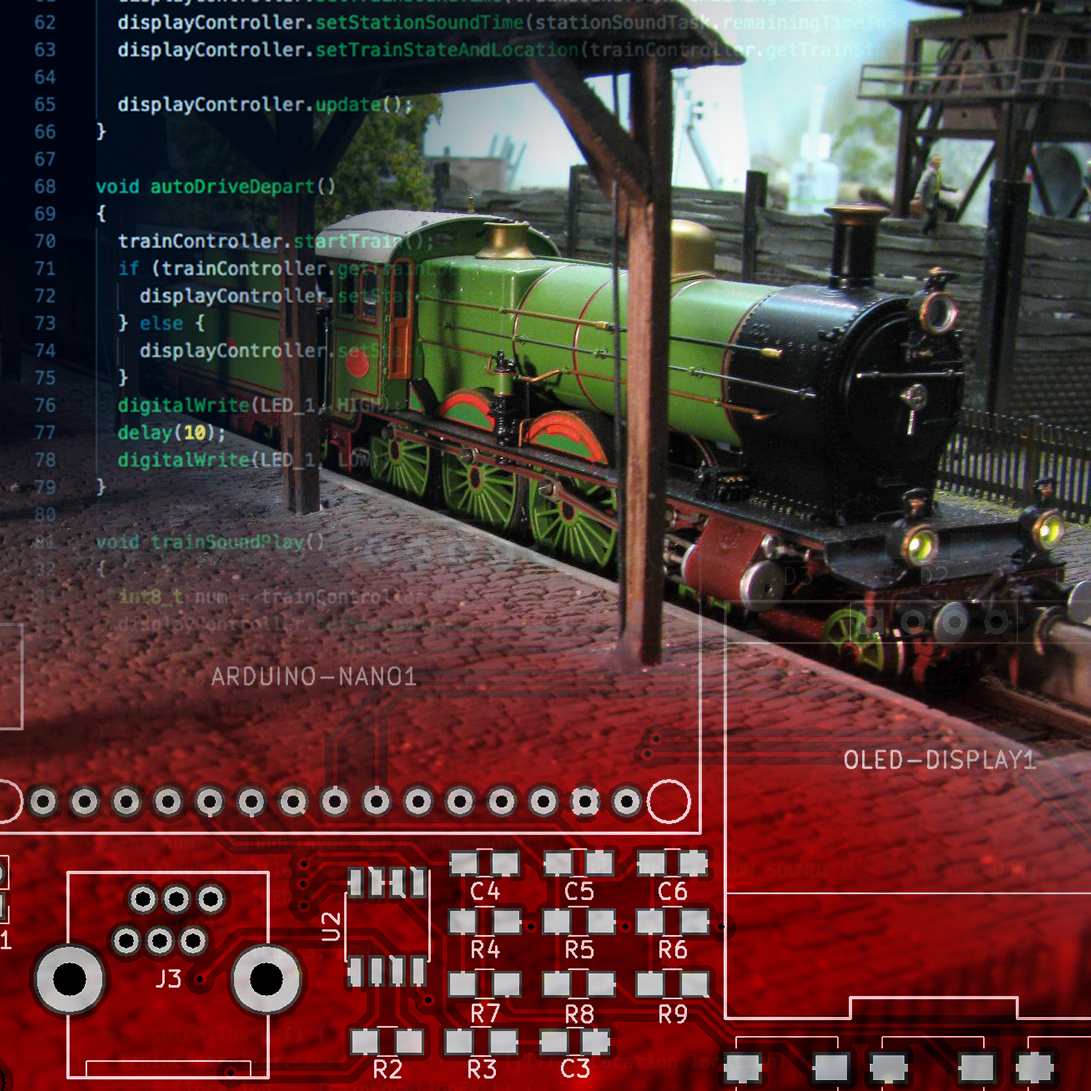
Writing the Software
After finishing the electronics it is time to work on the software. Since the train automator runs on an Arduino Nano, it’s time to fire up Visual Studio Code and start typing some C++.
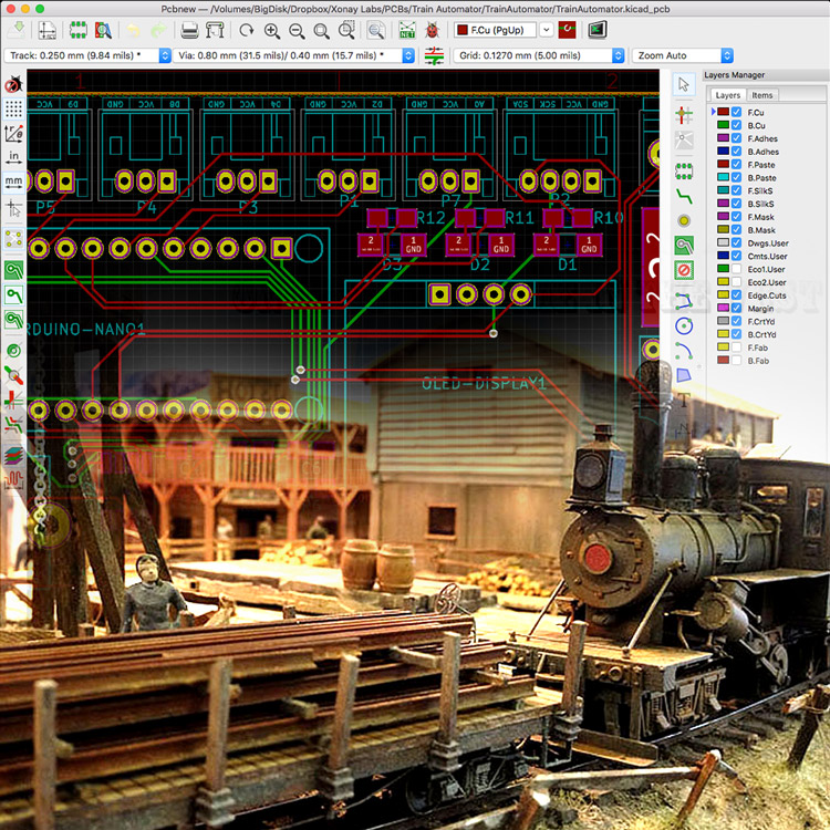
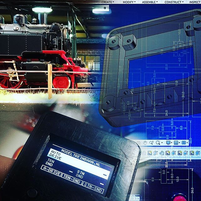
Train Automator:
Designing the PCB
Since the prototype turned out to be a success, it is time to work on a more professional solution: a custom PCB. Of course I don’t just slap an Arduino and a MAX485 IC on a board and call it a day. I use this opportunity to add some nifty features to the custom board. You know, just to impress my dad.
Train Automator:
Prototyping
As my regular readers know, my dad is an avid Model Train hobbist. And altough my interest is more on the digital side of electronics, every now and then our hobbies meet. After my recent Arduino powered analog clock project, I once again will work on a project for my dad: Let’s make his trains Arduino powered!
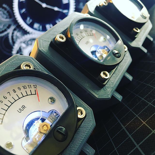
What time is it? Father's Day!
My technical enthusiasm is probably 99% inherited from my dad. So whenever I come across something fascinating, he is usually the first person to forward the link to. A little over a year, I came across some really awesome volt meter clocks. And due to his fascination of analog meters, he liked it even more than I did. Wouldn’t it be awesome to make one as a Father’s Day present?