
Every summer, me and a group of friends travel to the Belgian ardennes for a weekend full of sun, swimming, music, liquor and lots of fun activities.
One of the annual traditions is a Quiz mostly including bizarre questions presented by Quiz Master Tom. As the geek of the group I became the designated technical facilitator of this quiz.
Although we managed to the bring the quiz to pretty decent level (production wise, definitely not a high level of quiz questions … IYKWIM), one thing remained awfully unprofessional: we did not have any quiz buzzers, and solved this by letting the teams smash some pottery.
After lots of discussion last year, about who smashed first, the challenge for this year was clear: build my own Quiz Buzzers!
The shopping list
Time to collect the materials!
-
I still had a nice Adafruit Neopixel NeoMatrix laying around, a perfect display to present the Winner! (the one who pressed the button first …)
-
To control the Neopixels and register the button presses I would use a cheap and compact Arduino clone.
-
Because there probably is a lot of liquor involved during the game, and will be an aggressive battle, I needed some smashable durable big red buttons. Fortunately Staples sell those useless “Easy” buttons. 4 of those will do!

-
To cover the distance between the 4 teams, I took some old speaker cable. Long enough to reach a team in every corner of the room.
-
Additionally I grabbed some small parts like some resistors, a capacitor, screw headers, some experimental pcb, a smaller reset button, and a some old material to build a nice display mount.
Demolish the buttons!

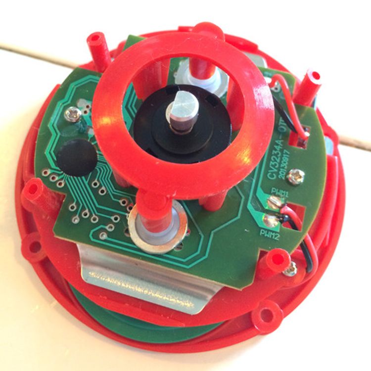
The easy buttons I bought appeared to be multilingual easy buttons. So after opening the button (4 screws on the bottom) I discovered it includes a rotational language selection button. I was a bit afraid this would make it quite difficult to get a on/off signal from the button …
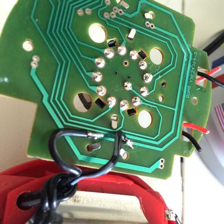
… fortunatly I turned out to be rather easy. Just by soldering my two wires to the bottom where one of the smaller side buttons made contact to the PCB was all I had to do.
After connecting my multimeter, it started beeping a soon as I pressed the button, so everything seemed fine. Time for the first test!
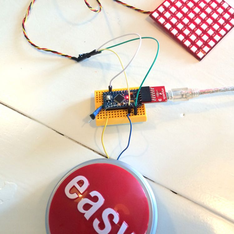
I quickly wrote a small test sketch to check out the result using a breadboard. And got some unexpected results. It fired some false button presses, and what was even more surprising was the fact that the behavior changed when I switched the wires.
It turned out the IC that was still in the Easy button (and still was still connected) interfered the signal. The solution was quite easy. “Gently” disconnect the IC by applying some artistic scratches…
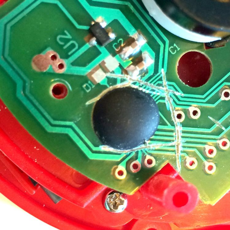
This solved the issue, and so I could continue to add the final wires to all 4 of the buttons …
Time for some electronics!
Let’s get technical
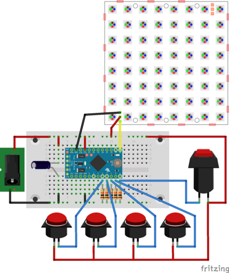
The schematics for this project are pretty basic. Never the less it’s always a good idea to try it out on a breadboard. The following diagram shows the way everything will eventually be connected:
As you can see: A lot of wires! The squared button on the right is the reset button. This button allows the QuizMaster to start the system for the next question.
Besides the wires, a few other items are noteworthy:
- The system is connected to a external 5V power supply. The Arduino (or USB Host) is not able to supply the necessary power for the full bright NeoMatrix.
- All buttons inputs are connected to ground using 10K resistor.
- And last, but not least: A 1000 µF, 6.3V capasitor to protect the NeoMatrix.
Blow up your NeoMatrix!
About that one capacitor … honestly: I did not put it in there until it was too late. Even so it probably would have not protected me from the stupid mistake I made: connecting the NeoMatrix while there was power on the system. I blew up the first Pixel. :(
I figured out I could continue to use the Matrix by bypassing the first LED, and connect the signal to LED #2. This worked, so now I had a 63 pixel NeoMatrix.
So, smart as I am, I instantly made the same mistake again! STUPID ME! Once again, bypassing the LED worked. Resulting in a 62 pixel NeoMatrix, so I got that going on for me, which is nice.
Continue with as if nothing happened
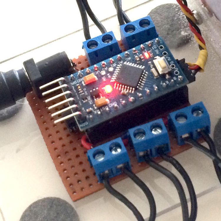
After I dried my tears and did some successful tests on the breadboard, I could start the soldering of a nice dedicated PCB including 5 screw header to connect all the wires.

Of course I wanted to mount the NeoMatrix on a sturdy socket. So after I once again looted my dad’s material storage room, I managed to build a decent display socket.
If any of you have good suggestion on how to bend this material without getting the air bubbles, please leave a comment down below!
Finally, I created a comfortable reset button from a old marker I stole from my mom’s drawer and some tape. The hardware part of the product was now finished!
The coding
Now, the hardware is only half of the product. Of course I still needed to write some code in order to get it to work. I’ll tell you more about the code next week, but for now I’ll just leave you clueless with a video of the endresult:
Room for improvements? Or questions? Leave a comment down below!