In the last few weeks I mostly focussed on the aesthetic of my Robot Arm project. Now that I finally received the necessary gears, It’s time to work on the transmission box.
The biggest challenge of my Robot Arm project are the joints that should not show any motors or gears. Because of this, I want to hide the motor inside main pipes. Because of this, I need a 90 degree angle transmission. Which I want to accomplish using a worm wheel. The last part I was waiting for before I could start my transmission box.
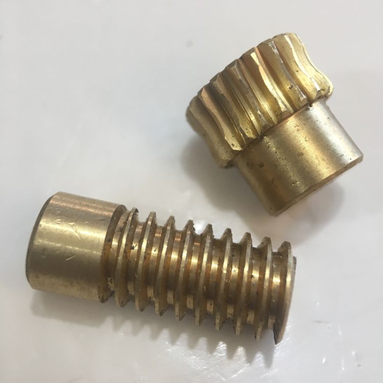
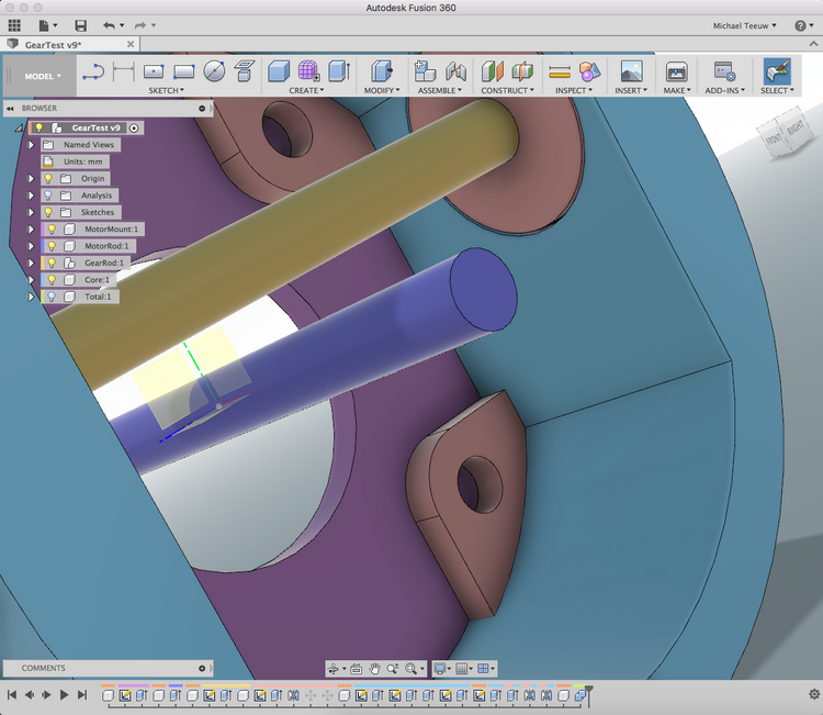
Now that I received the worm wheel and gear, it’s time to draw up my first version of the transmission box using Fusion 360. The added bennefit of using a wormwheel transmission is the improved power as a result of the speed reduction.
After a hour of drawing and one and a half hours of printing, the first version of the transmission box was ready to be mounted. Once again, I used FormFutura’s HDGlass to print the parts, since they were so kind to send me the necessary materials for free. And more important. Since I really like the quality and strength of the prints.
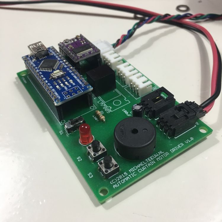
To give the motor a test spin, I used my spare Automatic Curtain Motor Driver which I created for my Automatic Curtain project.
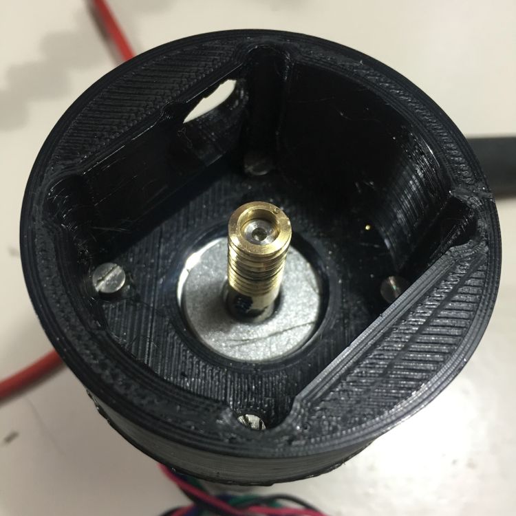
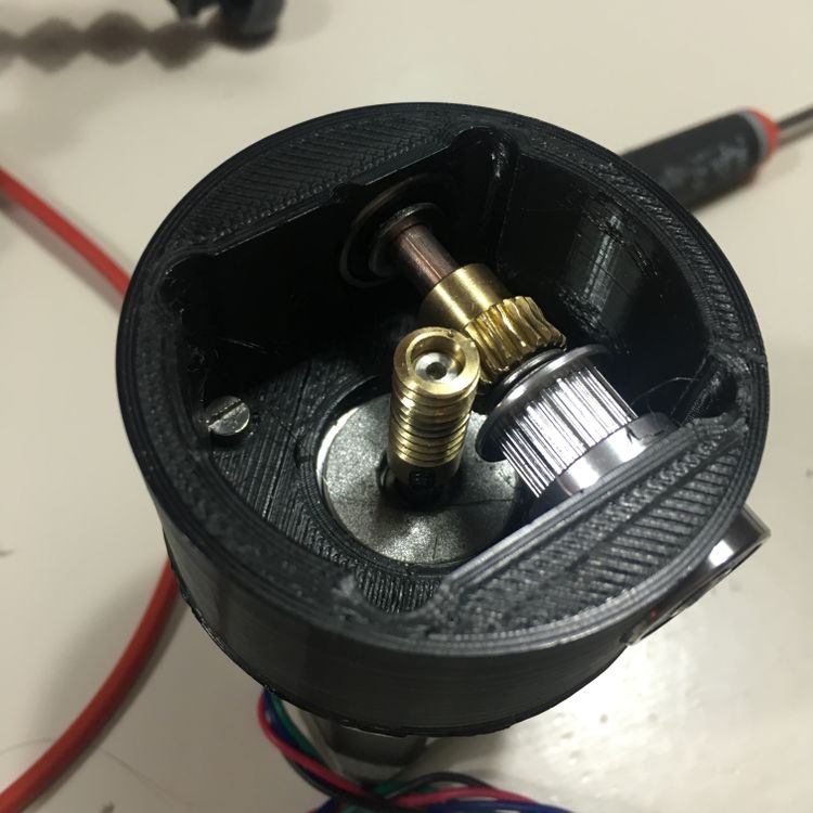
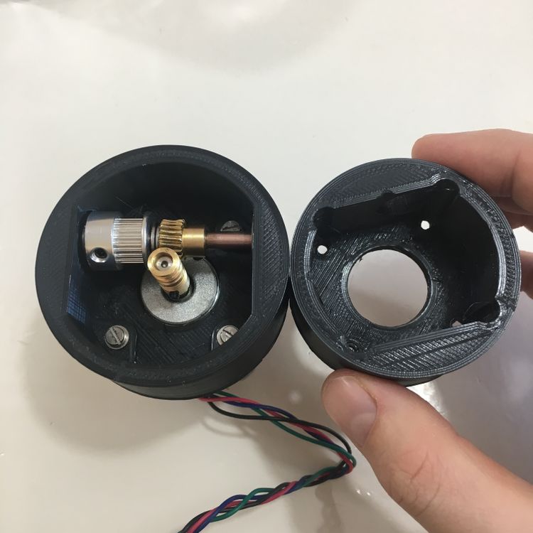
The most important part of the transmission box is the gear rod, which connects the worm wheel to a GT2 pulley. Which in it’s turn will eventually move the joint.
With the gear rod in place, it really starts to look like a transmission box!
Unfortunately, the gear rod needs to be pretty long … 54mm to be exact.
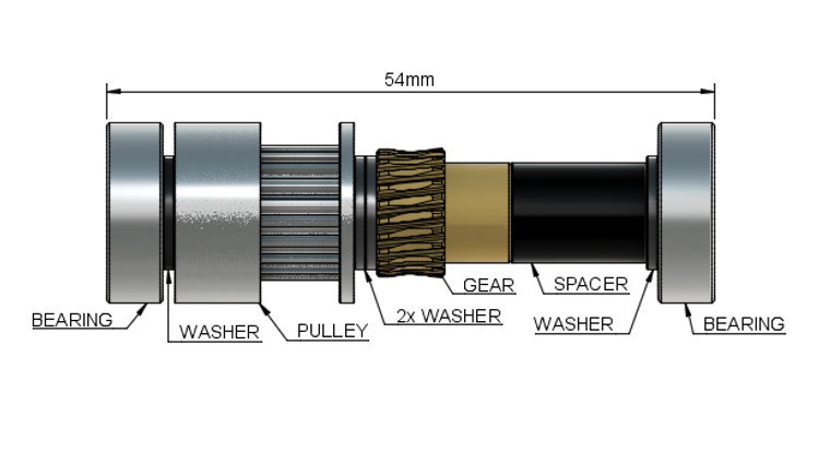
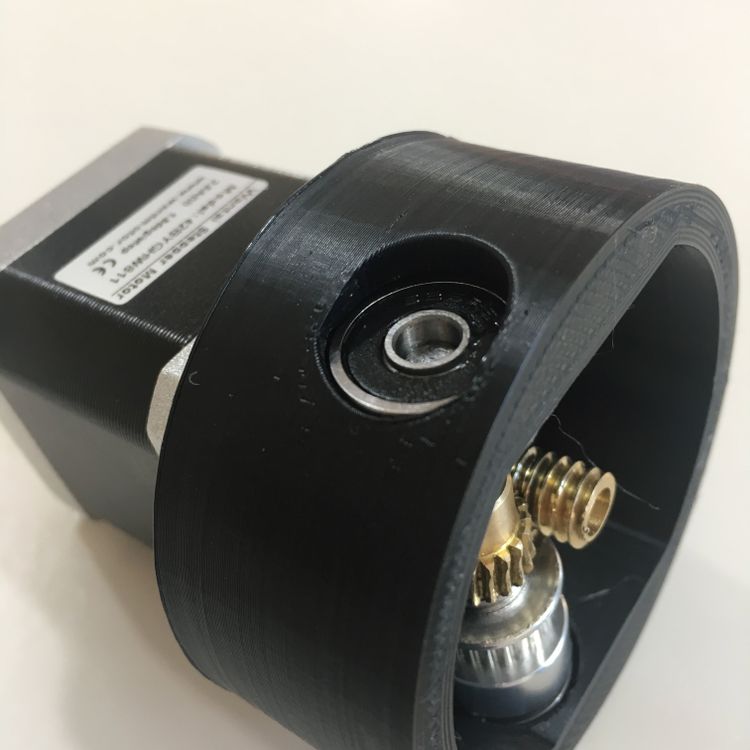
Which results in the following problem: The ball bearings stick outside of the transmission box. This is mainly because the motor shaft is in the center. Not only does this prevent me from mounting the transmission box inside the main pipe. But it also prevents the bearing to stay in place.
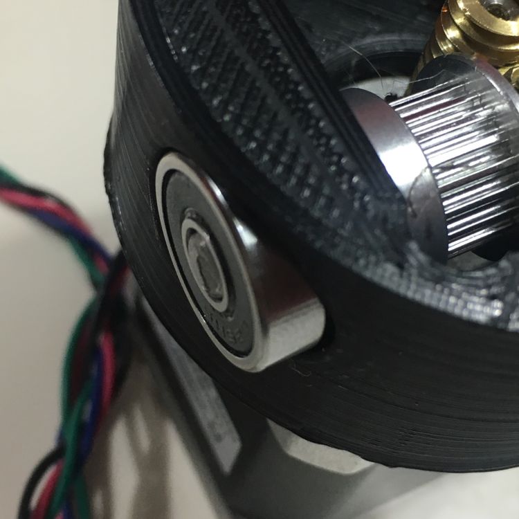
Never the less it give a good feeling of how this transmission box is going to work:
As you can see, it runs pretty well, but needs some small improvements in order to secure the bearings. As an experiment, I’ve printed a slightly larger version:
The added space allows me to add small ridges. Behind which I can keep the bearings in place.
Of course, this larger version won’t fit into the currently used 60mm diameter pipes. Which leaves me with 3 options:
- Use bigger pipes. Probably the easiest solution. But it also makes the robot arm a bit too bulky.
- Move the transmission box outside of the pipe, and make it part of the joint. This might work, but makes it more difficult to make it look nice.
- Add an extra gear and rod to move the worm wheel away from the center. Allowing me to move the main gear rod. This is the most difficult solution, but has some added bennefits, like changing the gear ratio.
As you might guess, I will go for option number 3. Which brings us back to the start of this post: waiting for the newly ordered gears to arrive.