During one of my many AliExpress shopping sprees, I recently found a cute little 1.3" High Resolution 240x240 pixel IPS TFT display. Till now, I only used monochrome 128x64 OLED displays, so this little toy sparked my interest. Using it would be a matter of connecting it to the SPI bus … or so I thought!
The display is driven by an integrated ST7789 display controller. The great people of Adafruit made an easy to use Library for this controller, so using it should be a walk in the park!
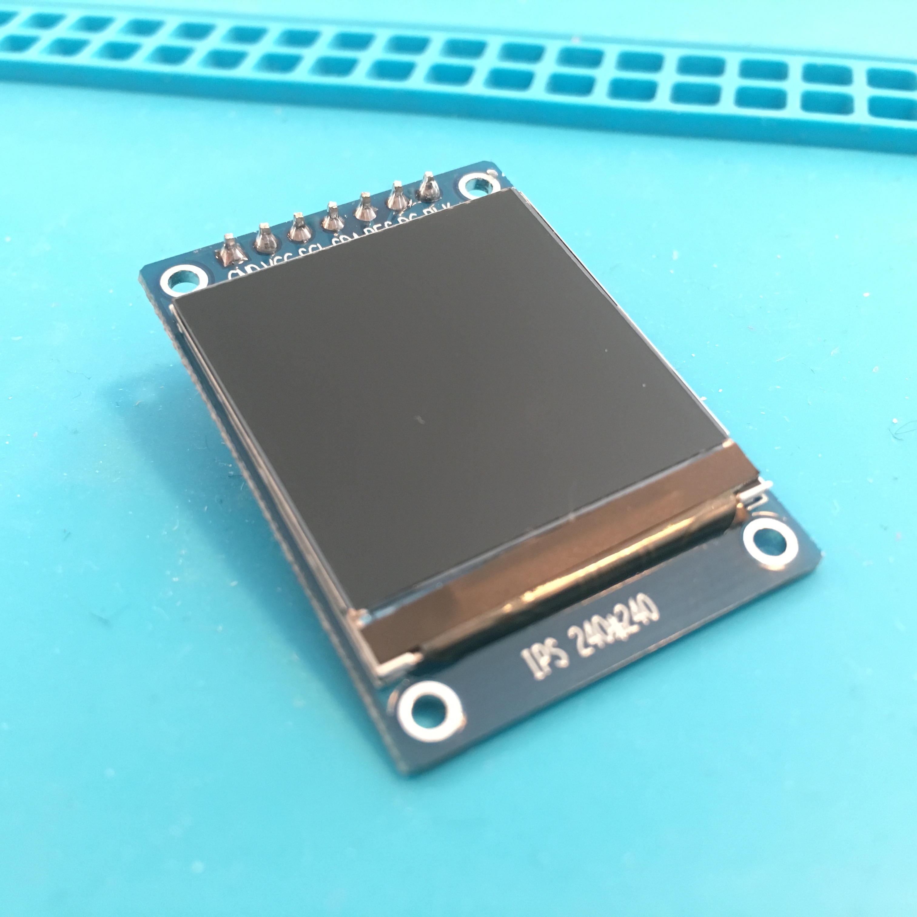
At least, that’s what I hoped … It turns out that the display Adafruit sells has one extra pin broken out. A pin that my cheap Chinese knock-off seemed to miss: the CS pin. Also known as the Chip Select pin. And although there probably is a way to get the screen up and running, I couldn’t find a software solution. Time for a more rigorous approach …

On the backside of the board, You’ll find the display connection ribbon. One of the 12 pins is the CS pin. Luckily I have a friend named Google who happened to know the pin I was after was number 8. So number 8, aka the CS-pin needed an extra wire. Unfortunately, the bad news didn’t stop here. It turns out that this board connects pin 8 to ground. So simply connecting a wire wouldn’t suffice. I needed to pull the plug on number eight …
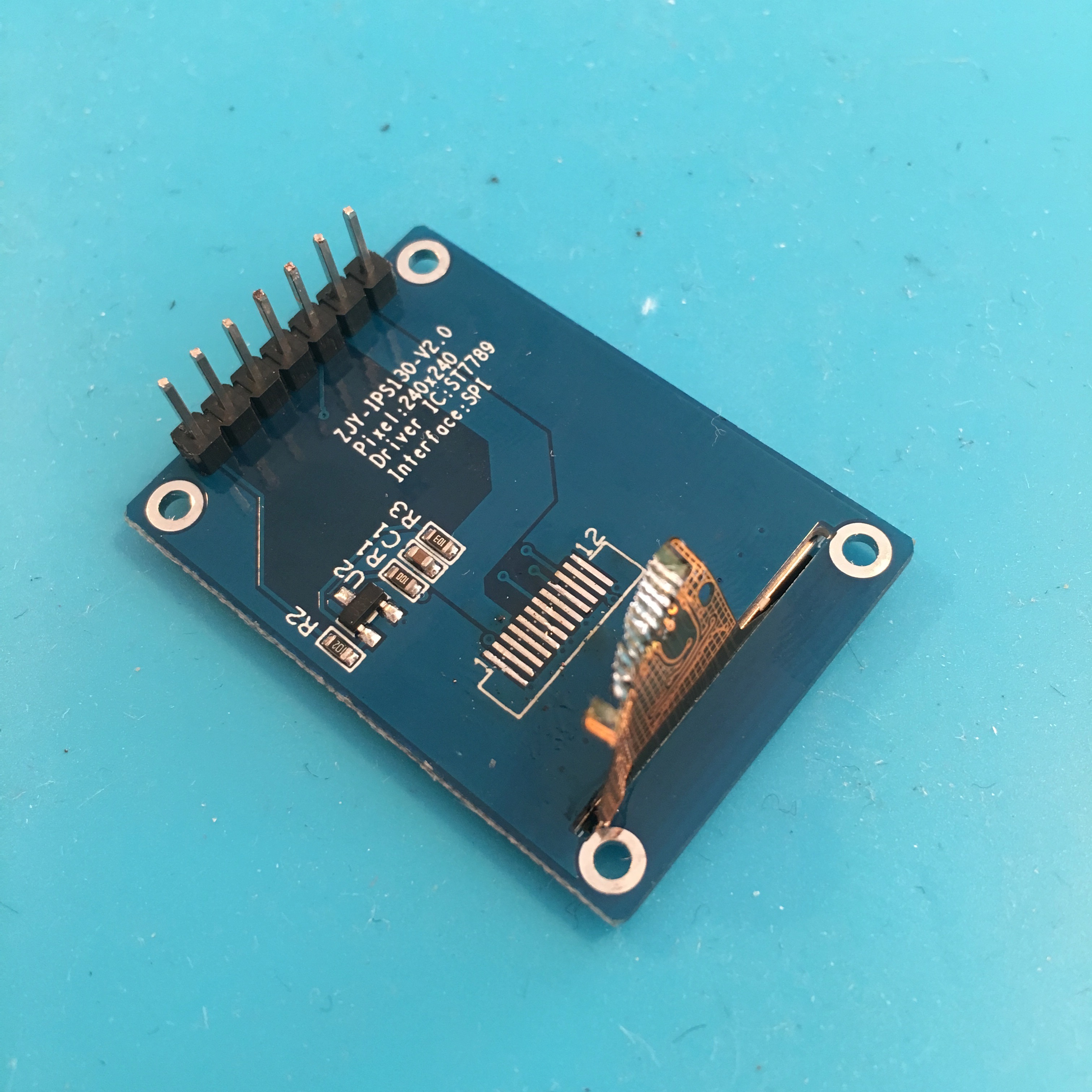
To do so, I first needed to disconnect the 12 pin ribbon cable from the pcb. There are two ways to do this: 1. Get out you expensive sophisticated rework station and carefully unsolder the 12 connections. Or: 2. Pry your bloody hot regular soldering iron in between the ribbon cable and PCB and use brute force to disconnect the two. I leave it up to you to guess which method I used. (A hint: my rework station is inconveniently stowed away in a closet, and I am lazy.)
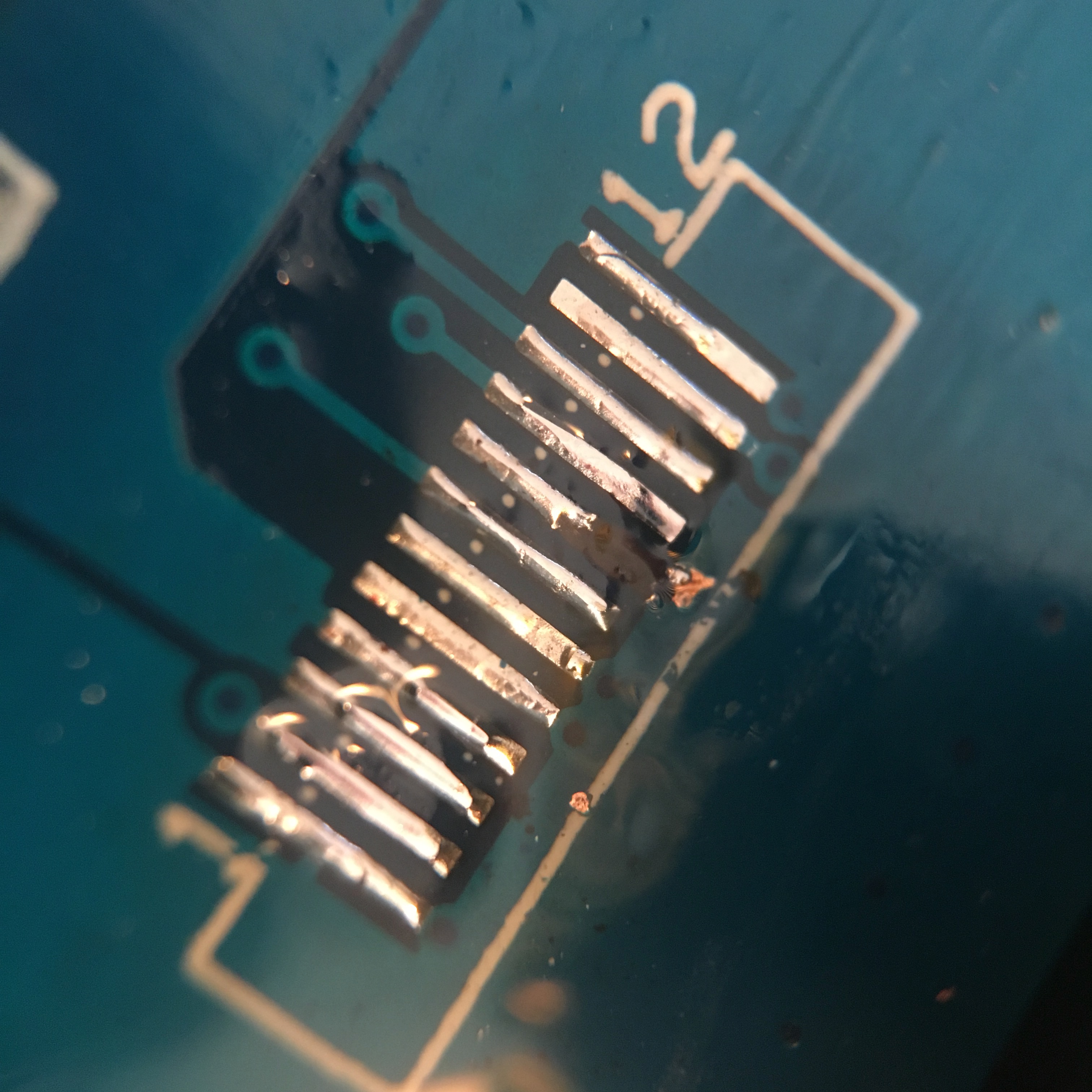
After cleaning up the solder pads, I used a sharp tool to scratch away a bit of pad number 8, disconnecting it from the ground plane. A quick and easy task after which I could try to resolder the recently butchered ribbon cable.

Miraculously resoldering worked out just fine, so all I had to so was add a small piece of wire two pin number 8. After that, I was time to connect the screen to a micro controller. Since the screen is a 3v3 device, I opted to use a ESP8266 (Node MCU) board, since these boards are 3v3 as well.
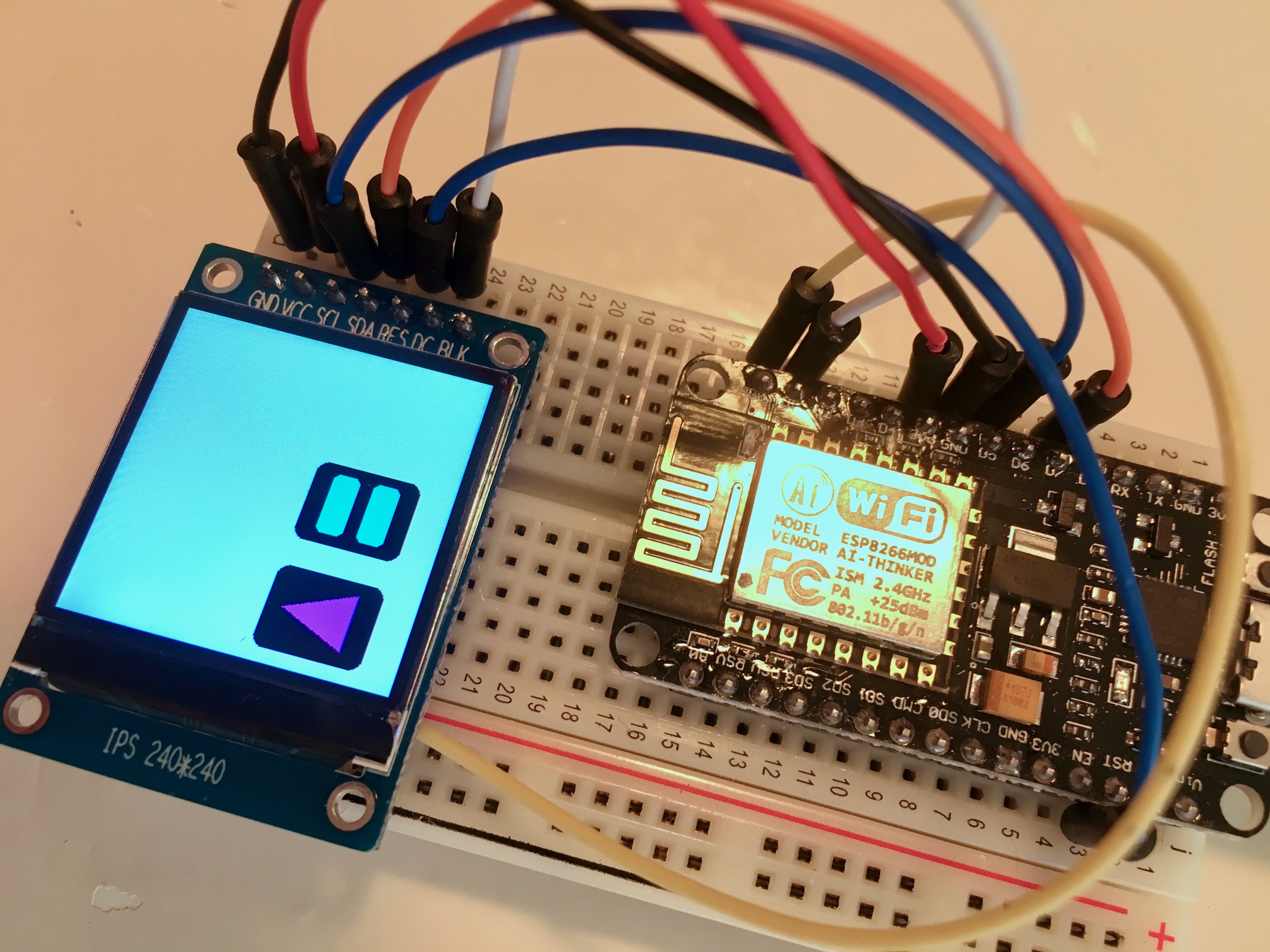
I used the following connections:
Screen        ESP8266
_____________________

GND --------- GND
VCC --------- 3V3
SCL --------- D5
SDA --------- D7
RES --------- RES
DC ---------- D1
BLK - - - - - (unconnected)

CS (wire) --- D0
And with that setup, I was ready to use Adafruits Library using the following defines:
#define TFT_CS     D0
#define TFT_RST    -1 // Use the microcontroller's reset pin
#define TFT_DC     D1
After uploading the firmware, i let out a sigh of relief: I didn’t damage the ribon cable (to my own surprise). The display showed some cure little text. Boy this display has a high resolution!

Unfortunately, the ESP8266 doesn’t really enjoy the Adafruit demo code … During the testlines routines, the ESP8266’s watchdog resets resets the controller. Probably because the for loops take too long.

A quick fix, is to add a simple delay(0) in all of the problamatic for loops. Thise will reset the watchdog on every iteration. Since we use delay 0, no actual delay is added (aside from the extra code that is executed).
// ...
for (int16_t x=0; x < tft.width(); x+=6) {
    tft.drawLine(0, 0, x, tft.height()-1, color);
    delay(0); // Keep the watchdog happy!
}
// ...
And with this, the graphical fun could start! I’m sure there will be a cool project coming along soon which could use 57.600 colorful pixels!
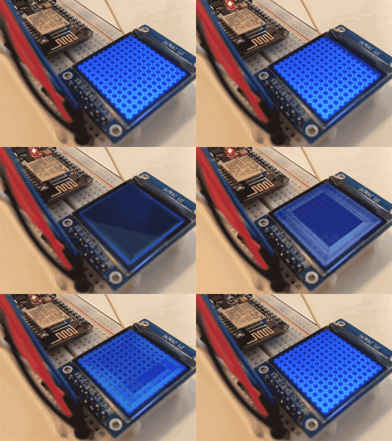
For you reference: this is how I connected the display, after I miraculously managed to not damage it …
Now, with this issue out of the way, please excuse me … It’s time for my next AliExpress shopping spree.
