Solving a Hot and Sticky situation
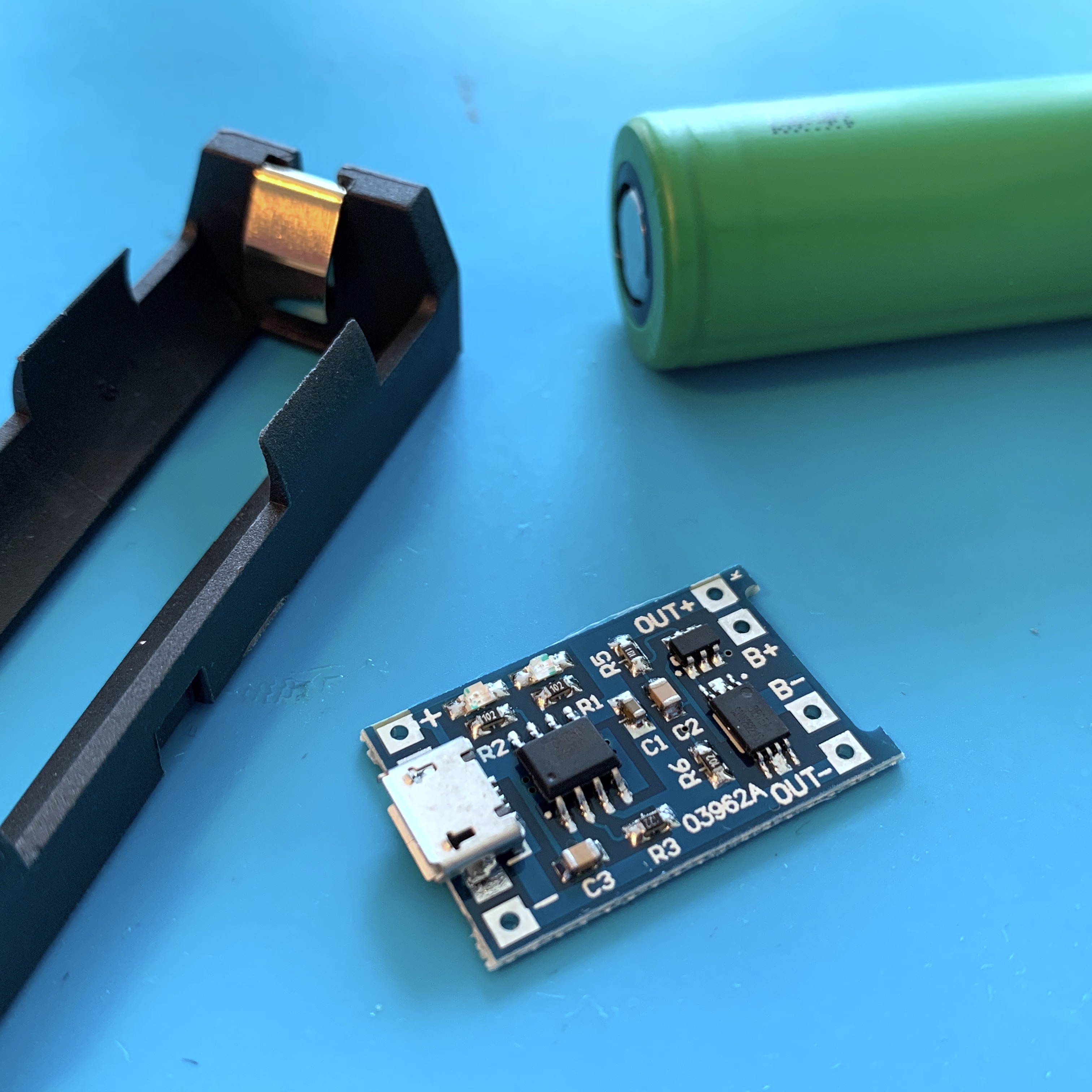
In the past few weeks, life got a little bit in the way of my maker-hobby. To make sure I got my monthly doses of tinkering, I decided to take on a quick and fun one hour project this weekend: solving a hot and sticky situation.
MusiCubes:
Touch Me Four Times
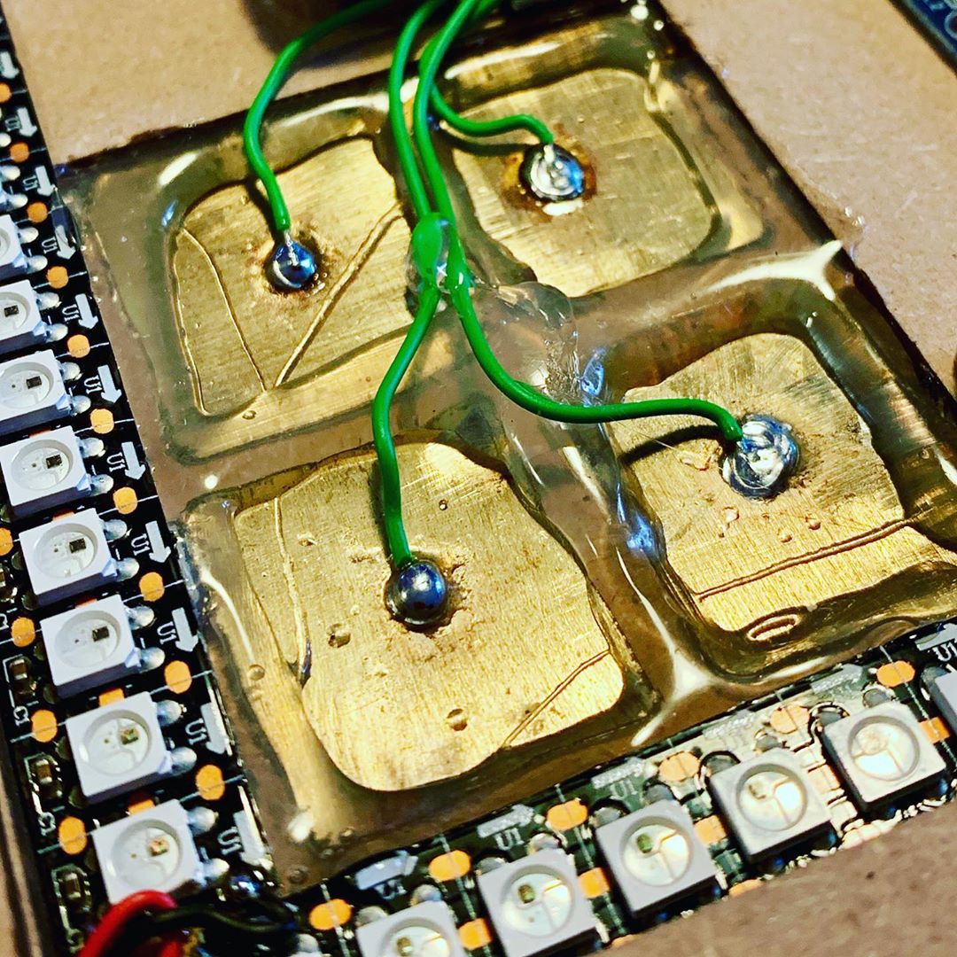
It’s been a few months since I’ve finished my MusiCubes Controller. And although most of the controller works perfect, there is one issue that is still bugging me: the false positives of the touch sensors. Time to fix this!
The Fire Proof Birthday Candle
This week we celebrated the first birthday of my youngest son, Luca. So it is time for him to blow out his first candle. Of course you can't trust a one-year-old to not set the house on fire when handling a candle, so we need to solve this with some electronics.
The Ridiculous Kitchen Timer™
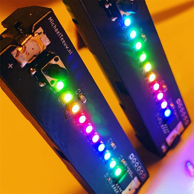
I’m a huge coffee addict. As for many of us, coffee is the core ingredient for my projects. And since I like quality coffee we own a manually operated espresso machine. If the grind is perfect, and you use the ideal brewing time, the coffee will be able to fuel any project. But how to measure the perfect brewing time? The Ridiculous Kitchen Timer™ to the rescue!
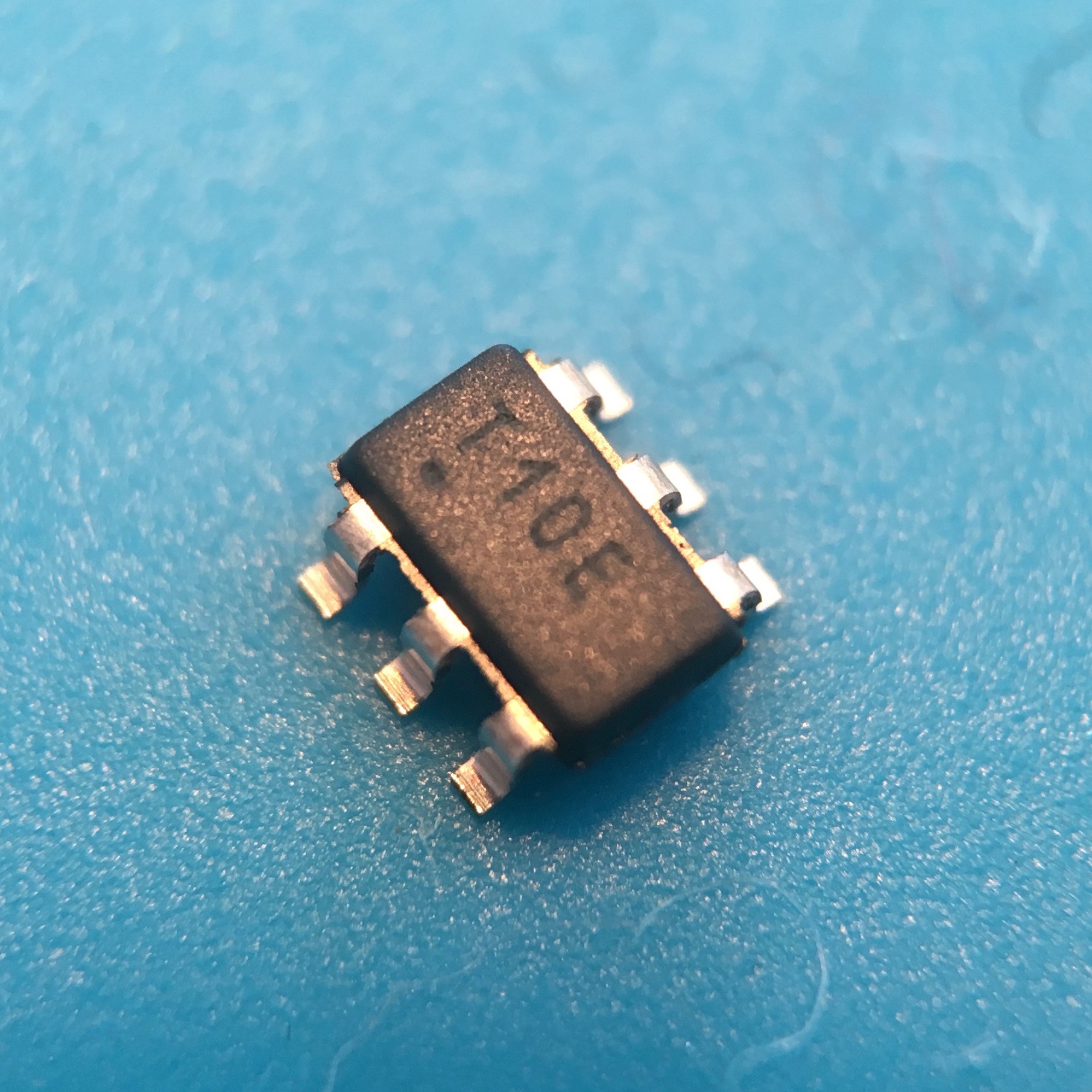
A Tiny Failure
If you are a regular visitor of my blog, you might know that (with a few exceptions) I’ve been posting a new blog posts every two weeks. Unfortunately I skipped this regular update last week, because I’ve been a little bit sick. Nothing major, but I didn’t want to contaminate my boxes of SMD components with germs. So after a few days of sleep it’s time to get back to business and start with something small. Literally.
57.600 colorful pixels!
During one of my many AliExpress shopping sprees, I recently found a cute little 1.3" High Resolution 240x240 pixel IPS TFT display. Till now, I only used monochrome 128x64 OLED displays, so this little toy sparked my interest. Using it would be a matter of connecting it to the SPI bus … or so I thought!
Activity Board:
Assembling the panel
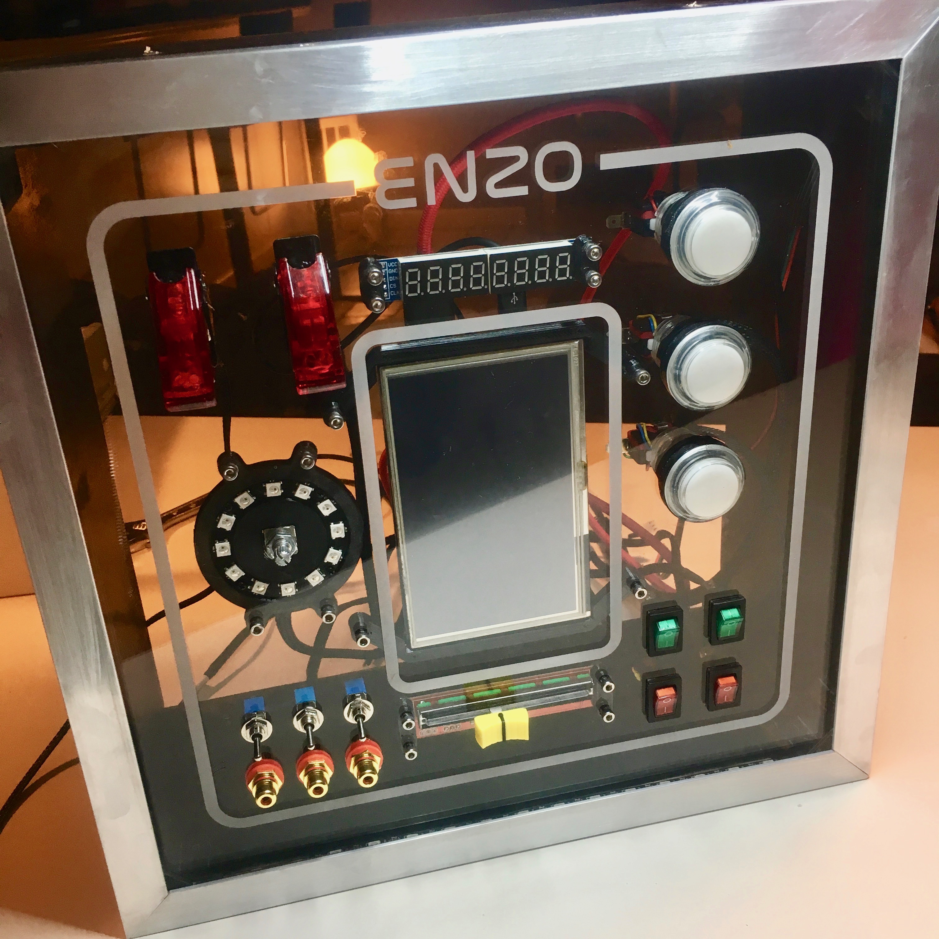
After a succesful intergration of the push buttons it is time to wrap up the front panel. With 9 switches, 3 buttons, 2 displays, 1 slide pot, 1 rotary encoder and a lot of LEDs, this includes a lot of wiring.
Activity Board:
Push the button!
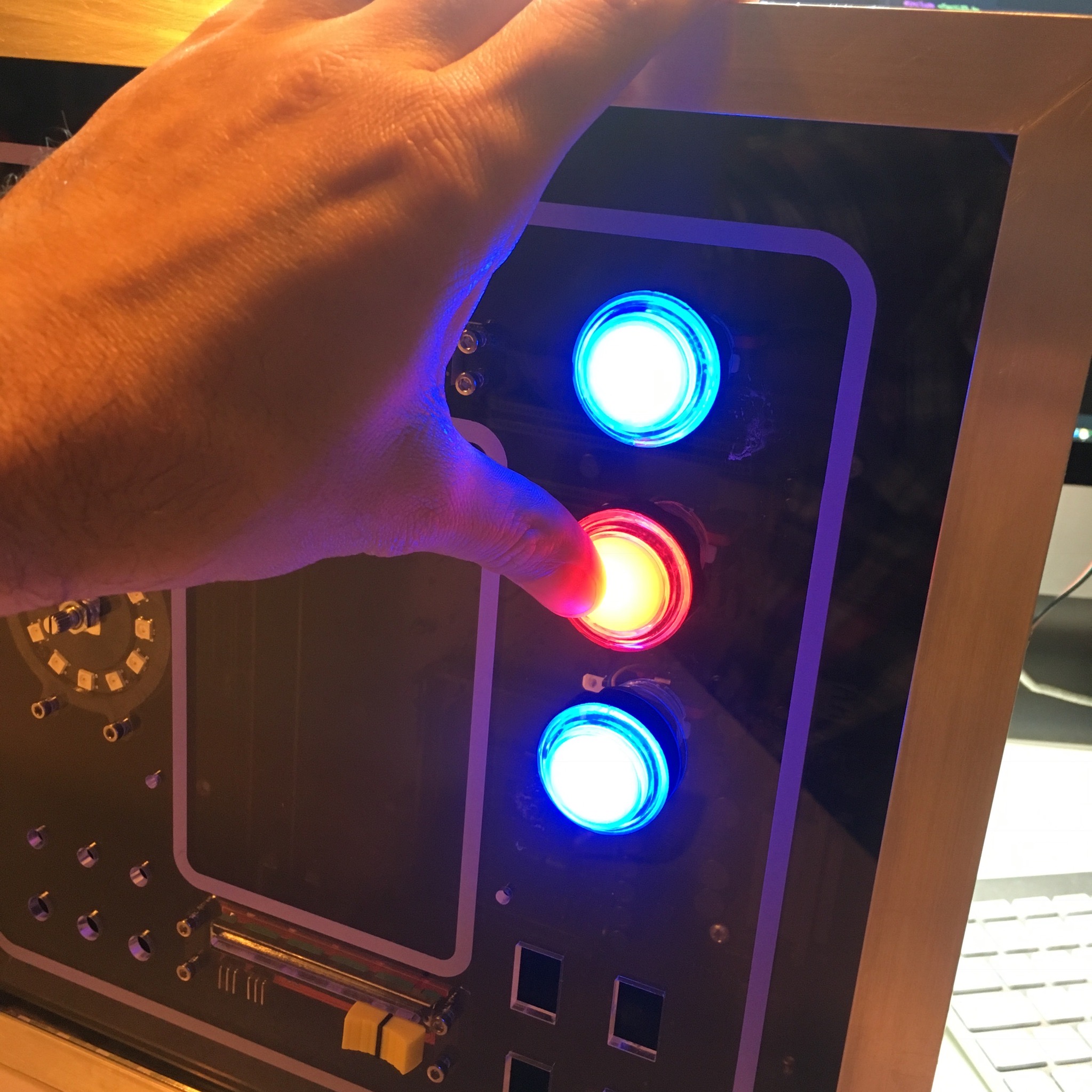
Now that the activity board casing is done. It’s time to start the wiring of all the components. A tedious job which I take way too serious.
It's getting hot in here!
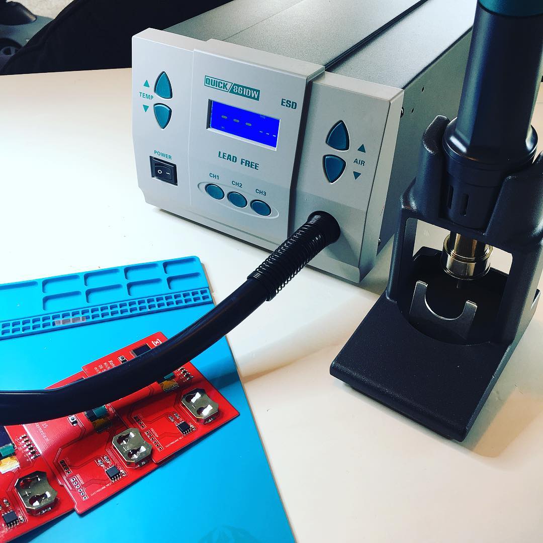
If you are a regular visitor of my blog, you might have noticed a slightly longer period of inactivity between my regular posts. In the past weeks I’ve exchanged my soldering iron for a nice juice on a sunny and warm beach. Regular visitors might also know that the mail man usually leaves me a nice package to come home to after my holiday. This time was no exception.
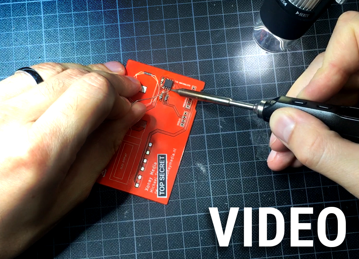
Electrocard:
Soldering
After my beautiful shiny new PCB business cards arrived, the fun could begin. Time to start soldering! And since a blog post about soldering isn’t the most exciting, I decided to make a video showing the full process.
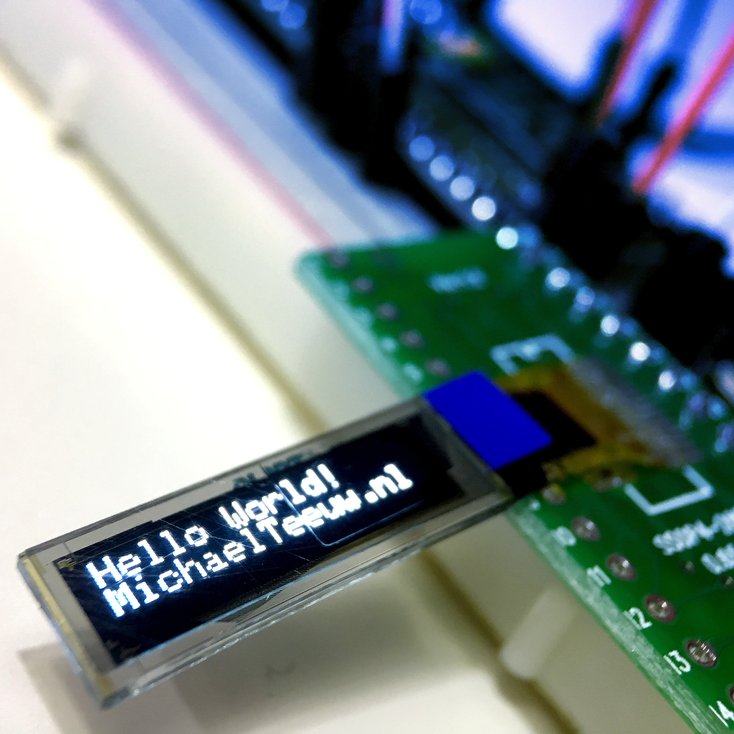
Trying out a Barebone OLED display
If you you are a tinkerer that likes to play around with Arduino’s and electronics, you’ve probably played around with a 4 pin I2C OLED display more than once. To step up my game, I thought it would be fun to give myself a little challenge and try out a barebone OLED screen without the convenient breakout board.
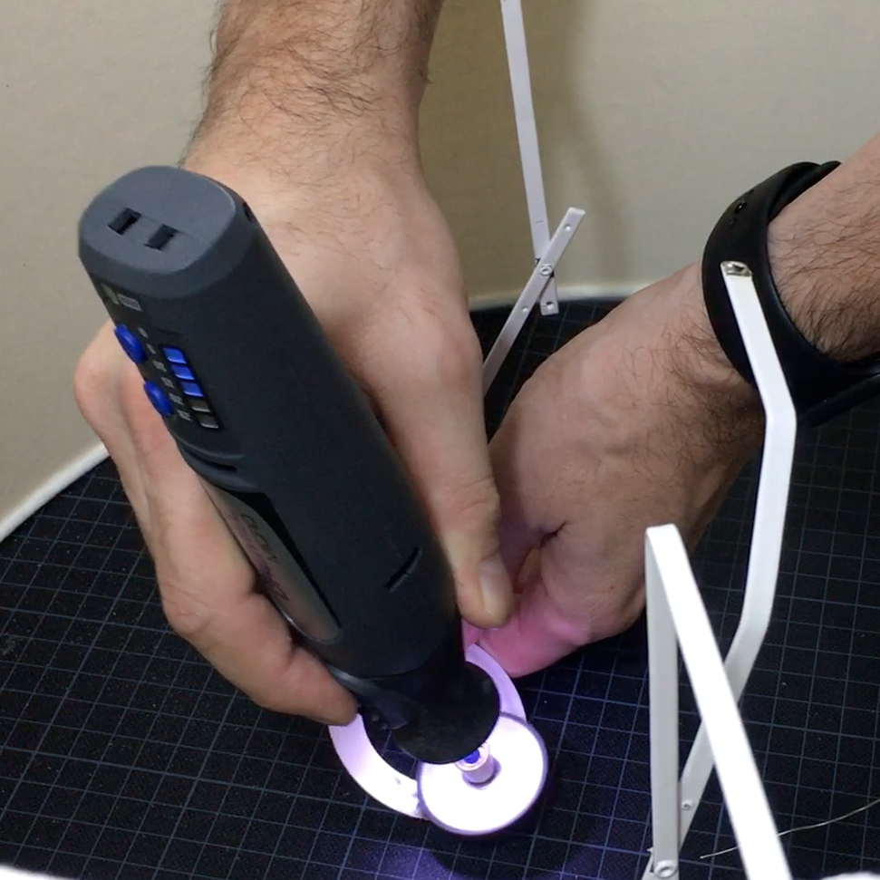
DIY Repairing
Not every experiment I do leverages the power of a 3D-printer. Sometimes it only contains a (hot air) soldering iron and a lamp shade. The end result? Some DIY repair work a corny video.
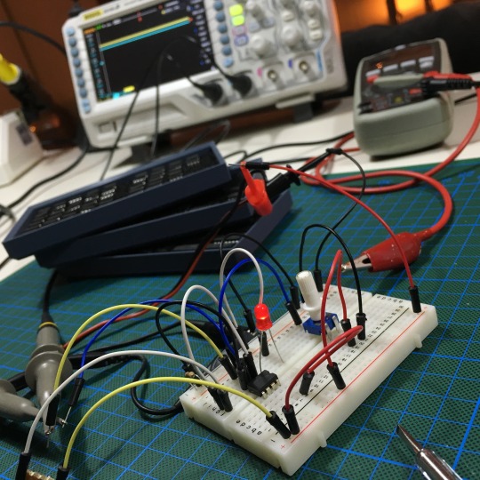
HomeSensor:
Keep an eye on the door!
With the software side of my Home Sensor up and running, there is only one technical issue to solve: the door sensor. A perfect moment to play around with an OP-AMP and Comparator.
HomeSensor:
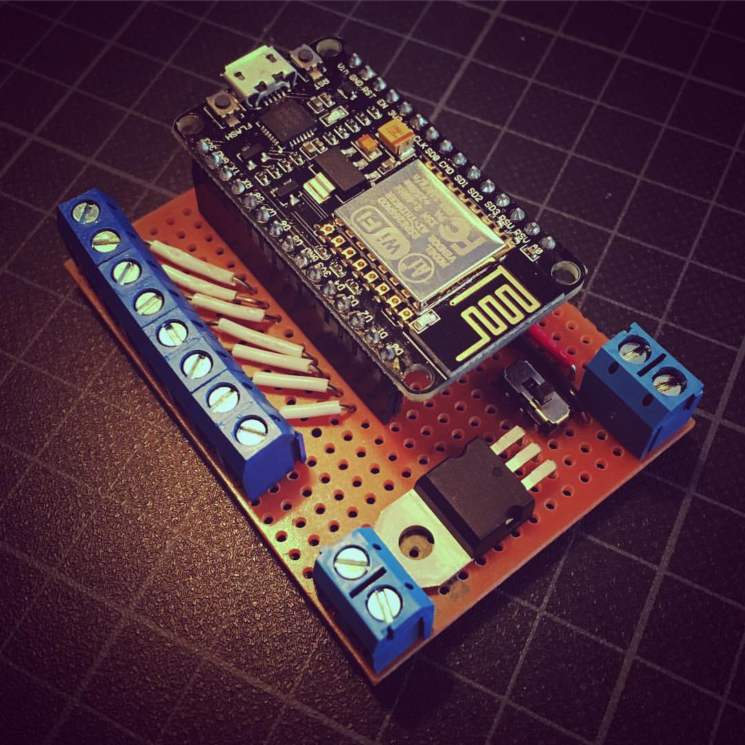
New brains for my Alarm
A little over 2 years ago I worked on a project in which I connected my alarm’s sensors to the web using my first Raspberry Pi. And while it still didn’t help me to lower the crime rate in my peaceful village, it turned out to be a very handy toy. Unfortunately, the system had some minor flaws, so it’s time to work on an improved solution.