Exactly one year ago I started working on a new project: a smartphone controlled automated curtain system. Of course, this isn’t something groundbreaking or new. The reason I picked it up is because I wanted to experiment with the mechanics, aside from all the electronics and software. To make it a bit more challenging, I set one special requirement …
While most automated curtain systems are controlled with two buttons (open and close), I wanted my system to work with specific presets (for example: 60% open). To do so, I need to keep track of the status of the lineair actuators. Because of this I will use a stepper motor to drive the lineair actuator.
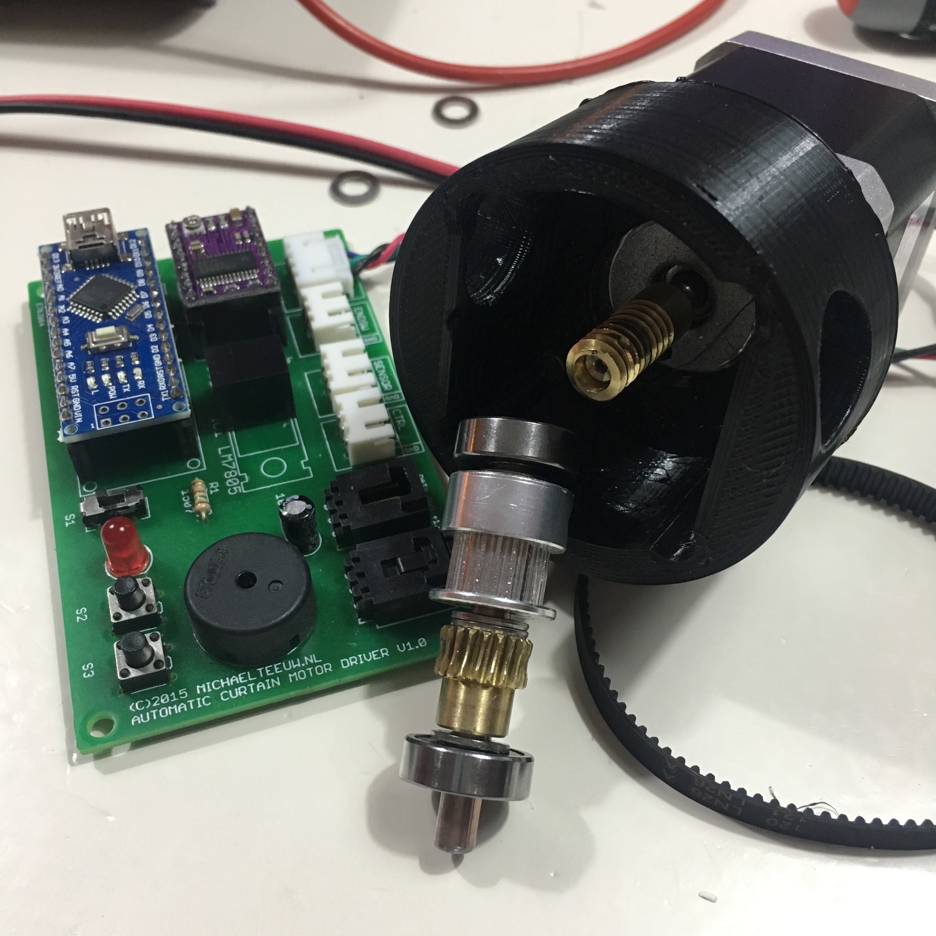
With this in mind, I started working on the first concept:
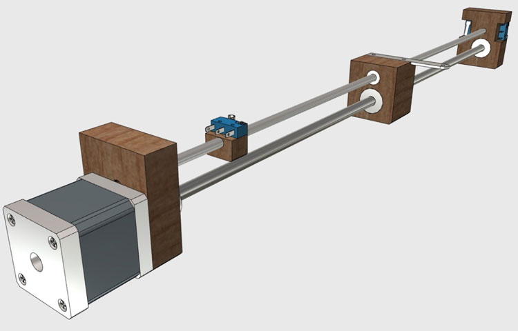
In this version, I use a threaded rod to drive the actuator. The benefit of using a threaded rod, is that the linear actuator will be strong and precise. So with this concept all drawn out, it’s time to make a proof of concept:
And that’s where the first problems showed up. As you might have noticed, the above video is speed up. This is because this design is way to slow for actual purposes. A side from the speed: it is extremely noisy. Conclusion: a threaded rod wasn’t the way to go.
Time for the next approach …
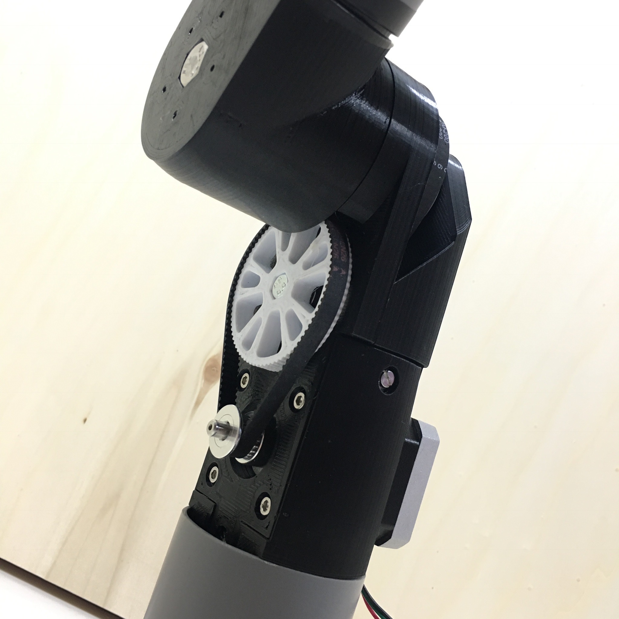
This time I used a belt and pulley system. To keep things nice and compact, I’ve used a curtain rail to guide the belt. But as beautiful as it looks, it has some problems as well. Since the belt drags thru the metal, it generates some wear and tear. In some cases the belt teeth even start grinding the opposite side. Especially when it pulls a load. It also is extremely difficult to adjust the belt tension. Since the system must keep working for years, this probably wasn’t the ideal setup.
Time to test out an other guide setup:
As you can see, this setup is much more stable. Of course it could use some linear ball bearings in the final version. But aside from that, it runs pretty smooth. But unfortunately, once again I ran into an issue: the final version of the lineair actuator must be 150cm long. To prevent the smooth rods from flexing, they need to have a diameter of at least 8mm. With the ball bearings around the rods, this would all add up to a setup which is way too bulky to fit behind my curtains.
Time to try out an other guide rail.

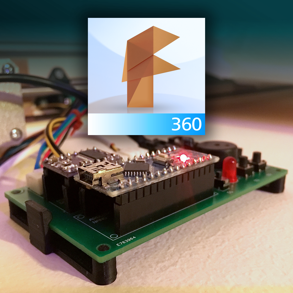
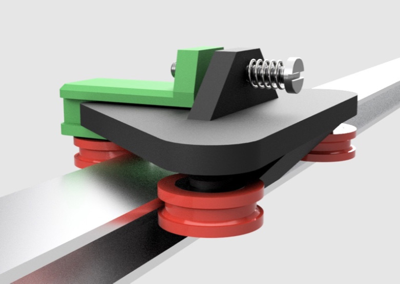
After I bought my Lulzbot 3D printer a lot of possibilities openen up. So with the help of Fusion 360 I designed the guide system in the image above. This system would run 3 wheels over a T or H shaped aluminium profile. A spring will tension the wheels around the profile and 3 ball bearings inside the wheels will smoothen the ride.
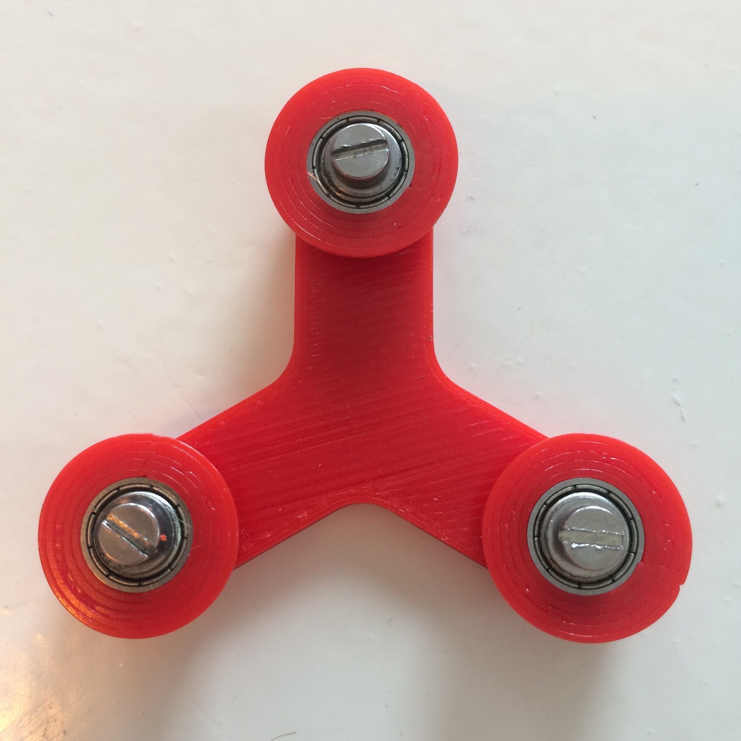
As a testcase I printed a version without the spring. And give it a go.
Although it wasn’t perfect it is pretty close. Of course, I need a way to fix and tighten the belt to this system, so once again I fired up Fusion 360 and started working on a some 3d designs.
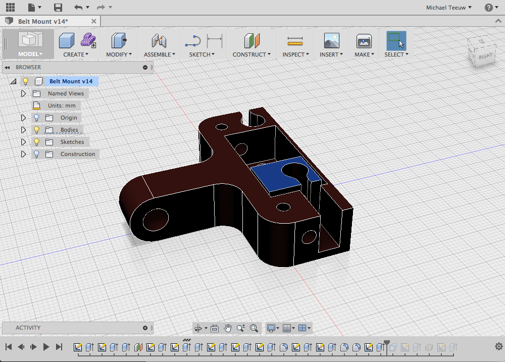
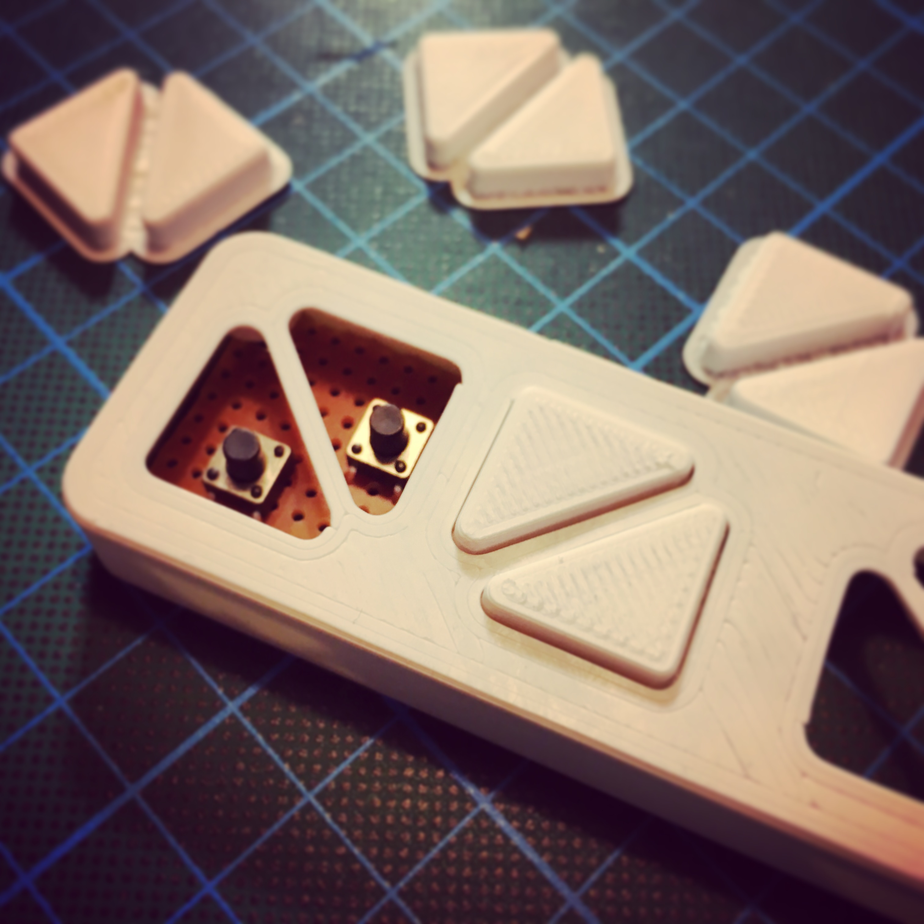
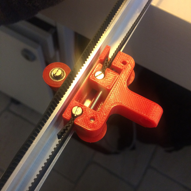
Honestly, tensioners are a piece of mechanics on their own. But with some experimenting, I think I’ve made an extreme robust and simple to use system.
Adding these two pieces together result in a nice piece of mechanics.
Slowly, I’m working my way to the best possible solution. But to be honest, I still wasn’t satisfied. As with all types of development (both hard- and software), there is always one important mantra: KISS. Keep It Stupid Simple! And with all those wheels, bearings and screws, I think it isn’t as simple and compact as possible.
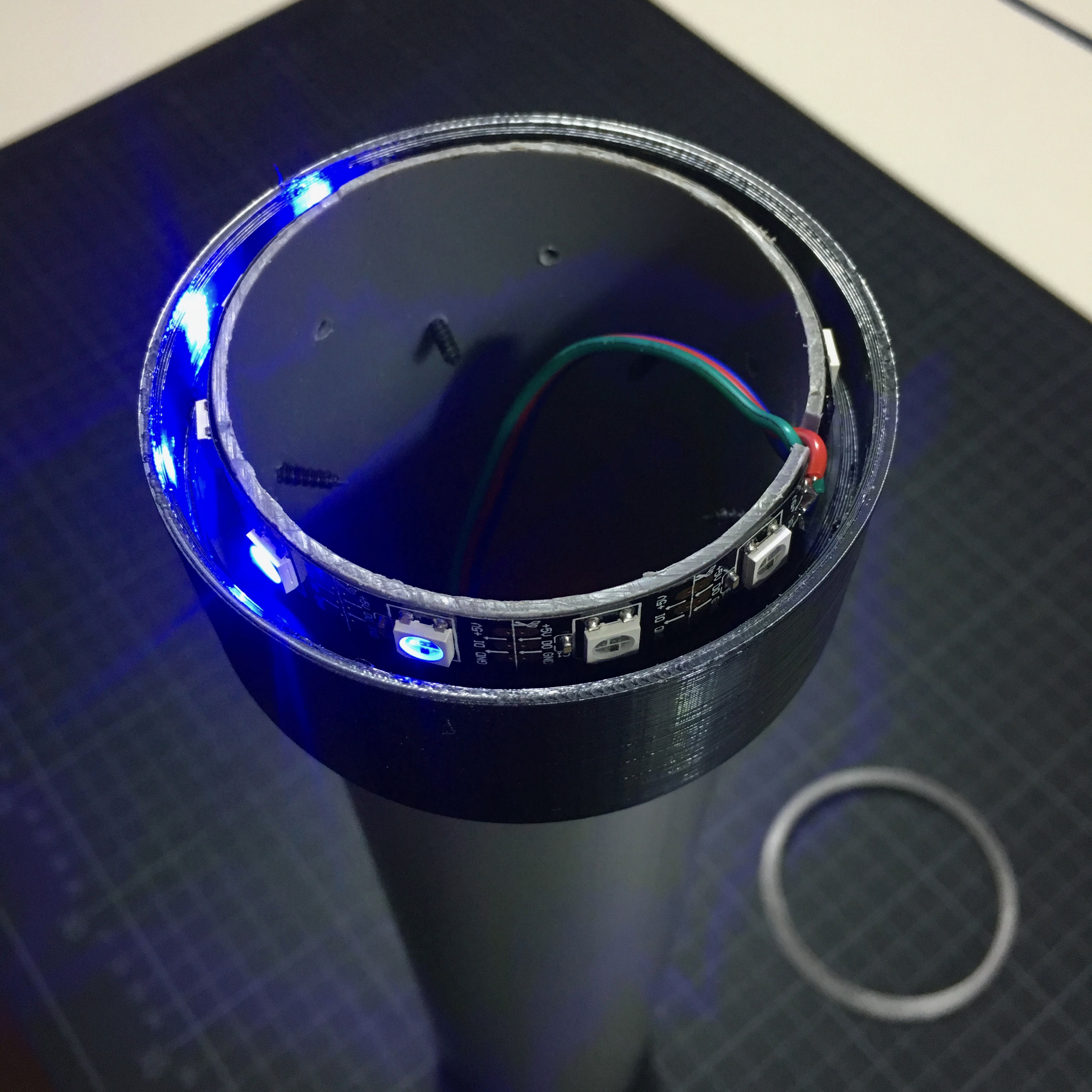
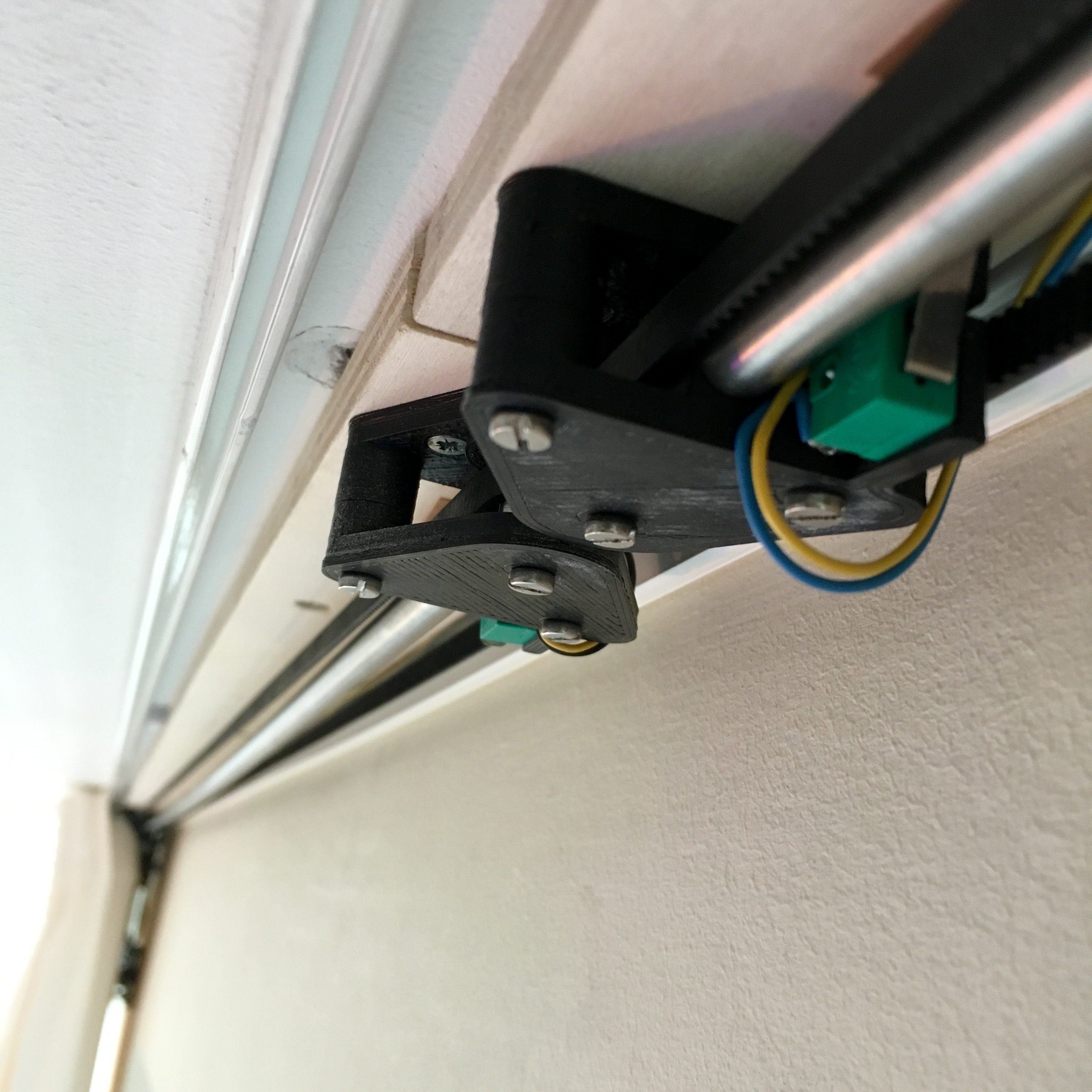
So one last time, I switched to an other solution. With the help of my 3D printer I gave the smooth rod version one more try. But to keep it compact, I used only one rod and placed the rod on the inside of the belt.
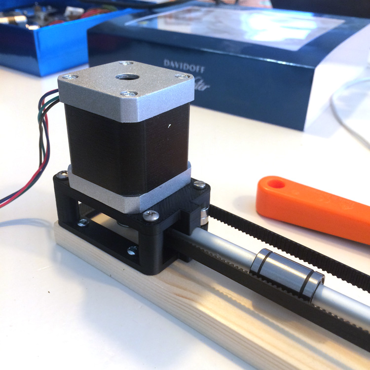
Of course, using only one road doesn’t prevent the bearing (and tensioner) from revolving around the rod, but since the tensioner will eventually be fixed to the curtain as well, this shouldn’t be a real issue.
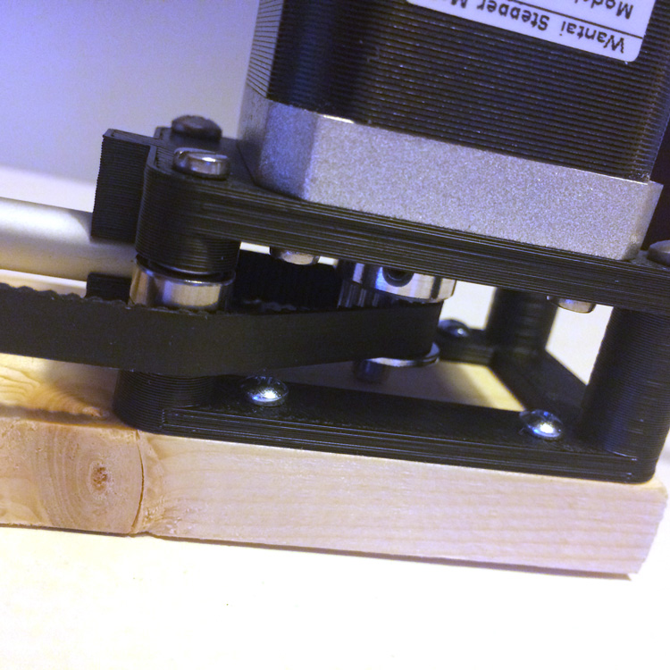
Using ball bearings anywhere the pulley needs guidance, I ensured a smooth run.
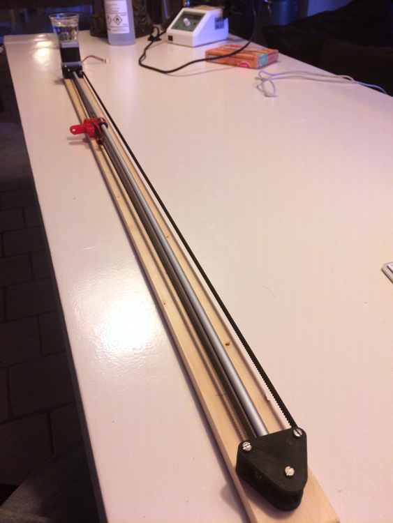
And with the original tensioner mounted to the linear bearing. It is time to give it a spin …
Of course there are still some pieces to be done:
- Add end switches.
- Replace the temporary aluminium pipe with a smooth steel rod.
- Redesign the tensioner to fix it to the linear bearing without the help of zip ties.
Will this be the final design? I hope to be able to tell you soon. For now, it surly is the cleanest, simplest and most robust version.
If you have any suggestions on how to improve my design, please leave a comment down below.
Automatic Curtains: Automatic Curtain Beta Testing