Exactly one year ago, I started my Annoying Dishwasher™ Project. With this project, my main goal was to silence the annoying beast for once and for all. Today, one year later, I continue this project to make some improvements by applying the knowledge I gathered in the past year.
Annoying Dishwasher: The Azure Dishwasher
After I removed the vocal cords off hell (also known as the ‘ready buzzer’), I connected my Dishwasher using an XBee connection to a Raspberry Pi. This allowed me to show the status on my Magic Mirror as well as sending me status updates via push messaged to my iPhone. One issue I ran into, though, was the fact that the connection to the internet had too many points of failure. The XBee connection could drop, the Raspberry software or hardware could fail, or the ethernet connection of the Raspberry could go down.
ESP to the rescue!
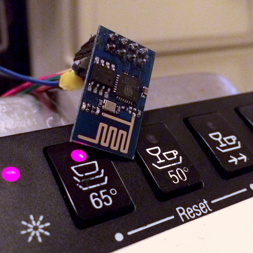
After the recent tests of the ESP8266 Wifi module, I decided my Dishwasher should get a standalone Wifi connection. Eliminating the need for the XBee and Raspberry Pi. Additionally, I want to replace the microswitch on the bottom of the dishwasher (used for automatic resetting after I open the dishwasher) by a magnetically triggered reed contact. Once again, to prevent failure. (The microswitch mount tends to bend after a few months of usage.)
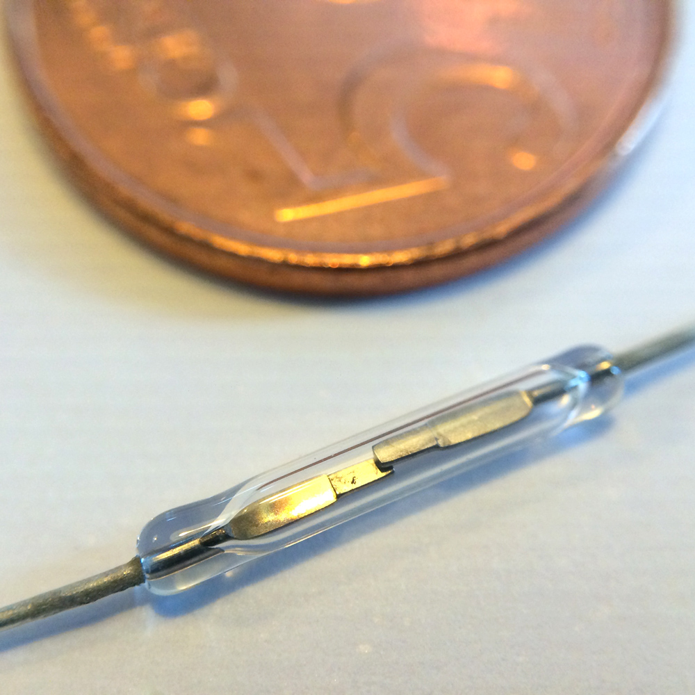
With this in mind, I had to redo the original schematics to meet the new demands:
- Change the operating voltage from 5v to 3v3.
- Add a 3v3 voltage regulator to the board.
- Change the reset function from a NC microswitch to a NO reed switch.
- Add a reset button to the board for testing purposes.
- Add screw connectors for all external connection for easy maintenance.
- Add a Heartbeat LED to the ESP’s spare GPIO pin.
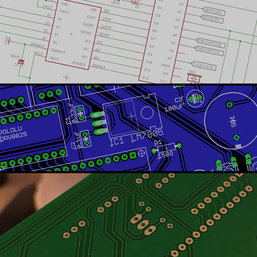
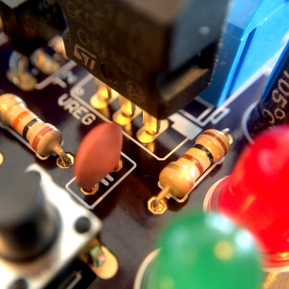
Because these changes result in a slightly more complicated board, I wanted to use this as an opportunity to create a professional PCB in stead of using some perf board. To do this, I once again used Eagle to update the schematics …
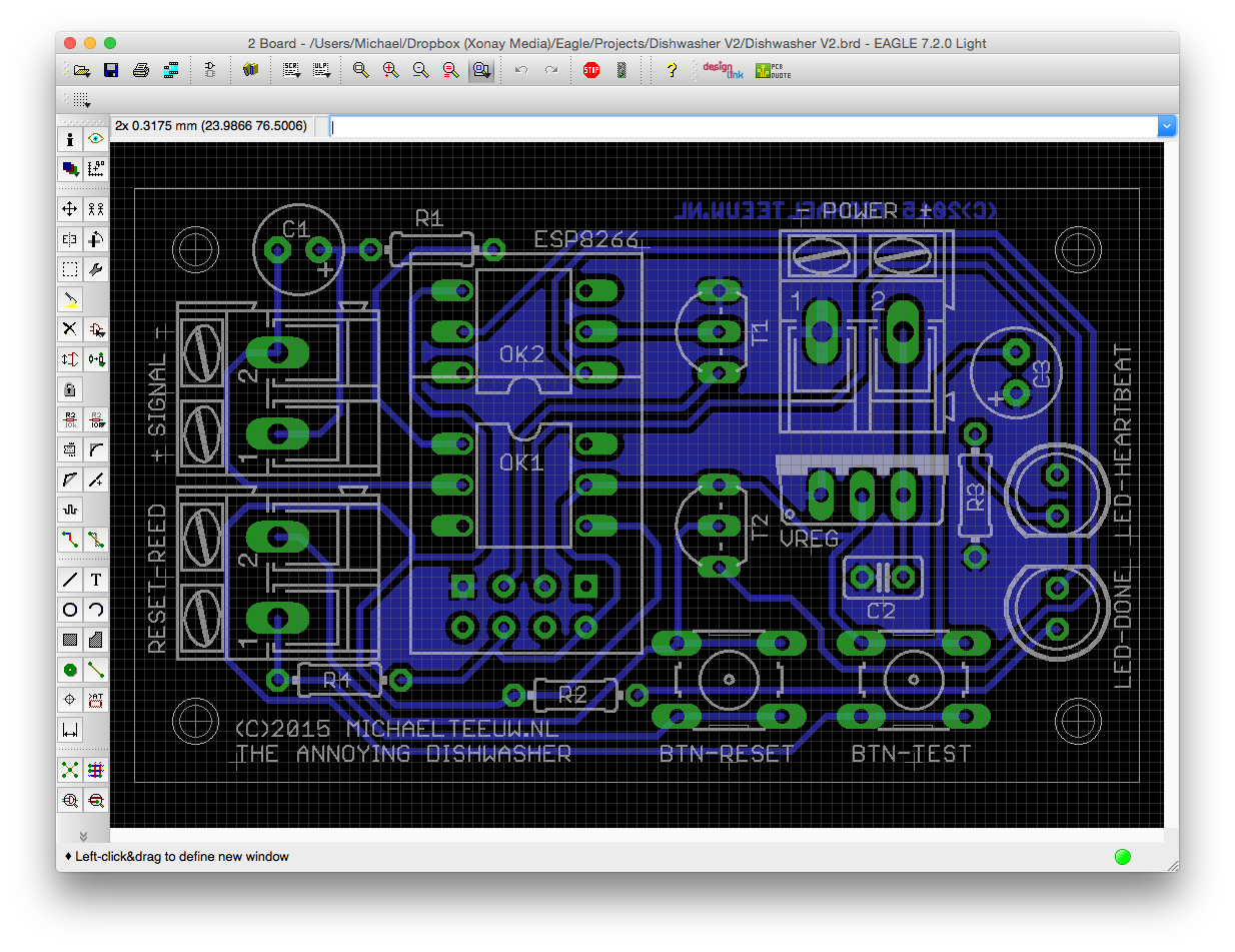
For the voltage regulator, I use the LD1117, so this part was just some copy and paste work from the datasheet. The reset reed switch was a bit more complicated, since I had to convert Normally Open signal to a Normally Closed system. A PNP transistor offers the solution and is added to the schematics (T2).
After I finished up the schematics, I started drawing the PCB in Eagle. Of course I could have used autorouting for this, but as most PCB will agree with me: manual routing is just more fun. A fun side note: my girlfriend thought that I was playing some sort of connect the dots game. She was right.
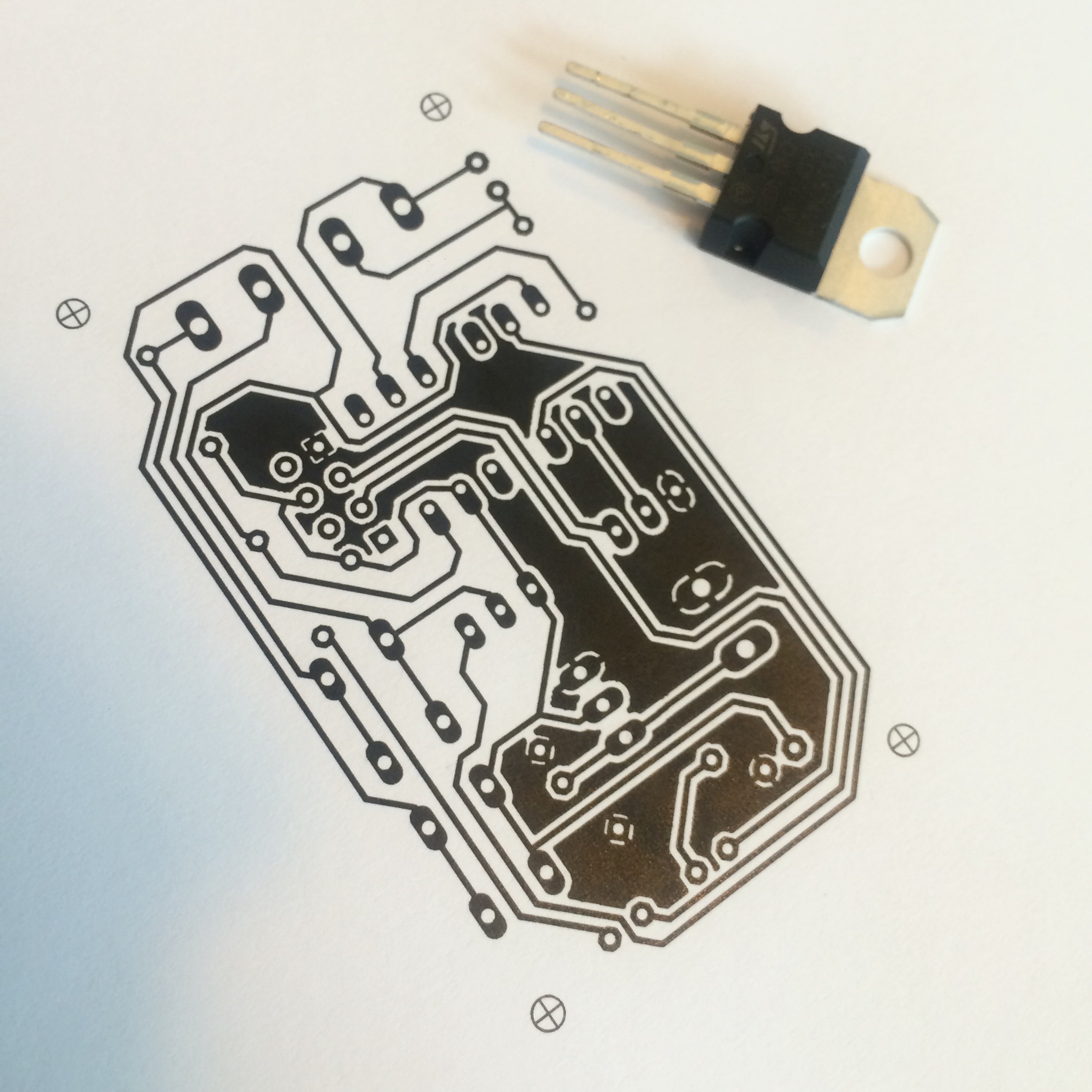
To make the challenge a bit harder, I only used single sided routes and did not use any jumper wires. I’ll be honest with you, it took me more than a day to finish this. A great way to waste some spare time! To check if every thing fits as I want, I made some tryout prints on paper:

This also reminded me of the fact that I need to mirror the backside if I print it. In this case it wasn’t necessary, but you don’t want to mess this up if you are going to make your own PCB’s.
The next steps.
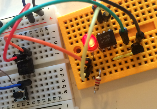
It is very tempting to send this file to a site like OSHPark, but since I don’t want to waste money and time on this, I go and do the sensible thing: test out my schematics on a breadboard before I order my PCB. Honestly: I should have done this before I started routing my board … but hey …

Keep an eye on my blog to see the test results. For now: let me know if you see any points of improvements. And if you spot a mistake: let me know and I’ll reward you by shouting your name while I solder the board!
Annoying Dishwasher: The Annoying Dishwasher v2 - My first professional PCB
