Do you know the joke about the relay on the ready LED? Well, it didn’t work. As told in previous ‘Annoying Dishwasher’ adventure, it turned out the ready led only turned on as soon as the dishwasher was opened. So the only way I could connect a ‘ready sensor’ to the dishwasher, is by using the original buzzer connections.
Annoying Dishwasher: The Annoying Dishwasher - The Sequel
My first idea was to connect a relay. Preferably using an optocoupler to separate the electronic circuits, and lowering the current on the dishwashers computer. Additionally I want to alter the ready signal behavior, so that the signal is permanent until you open the dishwasher, in contrast to the current situation where the dishwasher gives 2 one second signals every 15 minutes.
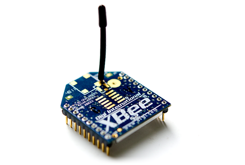
XBee - A cool name for a awesome device
Now, before I give away my final solution, I want to tell you a little bit more about the overall goal: I want my Dishwasher to communicate with one of my Raspberry Pi’s. Of course this could be done by connecting an (other) Raspberry or Arduino with Wifi connection, but that would be a bit overkill. Especially since I might add some sensors to other beeping household appliances. The solution? An XBee Module!
When configured (more about that later), all I need to do is connecting XBee’s pin DO1 to GND when the dishwasher is ready to send my main Raspberry the info it needs.
This would be a piece of cake if i’d use a relay, by just letting the relay feed itself as soon as it turns on once.
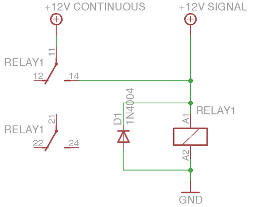
Above diagram shows how a relay can keep itself on once it gets a one time signal. The diode D1 is merely used as flyback diode: a protection against the generated induction load.
But as expected, the 3000Hz square wave was insufficient to reliable pull the relay all the way up. Adding a capacitor did not solve it. The relay was just way to slow for the square wave signal. So there you have it: the relay just wasn’t a fair opponent for the dishwasher. Pure strength wasn’t the solution. I needed finesse and technical feats in my battle against the annoying beast.
Breadboarding
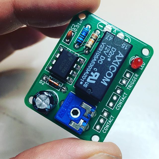
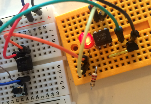
Time to get the breadboard! This job should be solvable with only a few semiconductors. No need for cumbersome relays. Drop in a few optocouplers and a transistor. Add a cable here an there, some resistors and a LED to make it look a bit more fancy, and whoop! There it goes!
Ok ok, to be honest; it took me an hour or two to get it working like desired. But hey, it’s the end result that counts!
After the prototype worked as expected, the next step was to make a more permanent solution. But before running to the soldering iron, I figured it would be a good idea to draw out the current schematics. The additional benefit of this is the fact I can share it with you. To draw diagrams like these, I use the free version of Eagle. It’s very easy to learn, so give it a try … Anyway, back to the diagram:
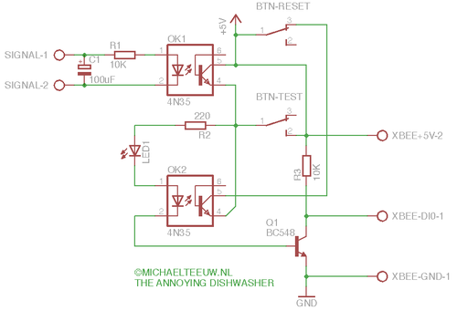
Get it? Good … let’s continue with the next step … Just kidding, no worries, When I see diagrams like these, they usually scare the hell out of me, so I’ll explain every component for you. Starting from the top left.
- SIGNAL-1: The 12V+ buzzer connector of the dishwasher.
- SIGNAL-2: The ground connector of the dishwasher.
- C1: This 100uF capacitor was added after I created the final product. The dishwasher gives some unwanted signals as soon as the waterpump turns on. A capacitor like this filters out unwanted noise signals.
- R1: A 10K resistor to make sure I don’t kill the first optocoupler by the 12v square wave I get from the dishwasher.
- OK1: The first optocoupler. This one separates the dishwasher’s electronics from my electronics. As soon as pin 1 & 2 get sufficient power, pin 5 & 4 will be connected.
- +5V: +5 volt input to power my circuit.
- BTN-RESET: A button mounted on the bottom of the dishwasher. This will reset the system as soon as I open the dishwasher, just by disconnecting the power to the second optocouper.
- LED1: A LED to show the current state. If the LED is on, the dishwasher is ready. If it’s off, the dishwasher is still busy, or opened.
- R2: Since the circuit is powered by 5 volts, I need a 220K resistor to protect the LED and the other semiconductors.
- BTN-TEST: It’s useful to add a test button. Not only will this save 15 minutes of waiting time (the shortest washing program takes 15 minutes), but it also saves me a lot of unhealthy food I need to eat in order to generate test dishes.
- OK2: Since this optopcoupler is connected to OK1, it is turned on when the dishwasher gives it signal. When it’s turned on, it enables a constant power via pin 5 & 4 keeping the full circuit (including itself) on without the need of a signal on OK1. So basically, this does the magic.
- Q1: A BC548 transistor in series with the LED and OK2, gives the output signal to the XBee Module.
- R3: The XBee Module has it’s own pull down transistor. But I’m having some troubles with it. (I created a workaround in the software). I added this 10K resistor in the diagram as a more permanent solution, but to be honest, I did not yet add this one in the final product.
- XBEE+5V-2: A +5V to the Xbee Module.
- XBEE-DIO-1: The connection to the Digital In 0 of the XBee Module.
- XBEE-GND-1: The ground connection for the XBee Module.
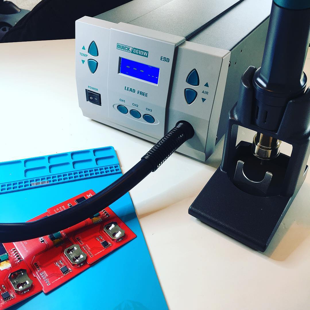
With the completed diagram, I took a small sprint to the soldering iron, and started the assembly of the final product.
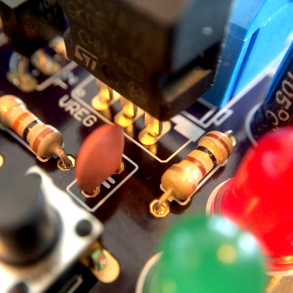
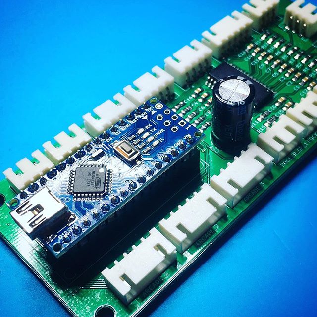
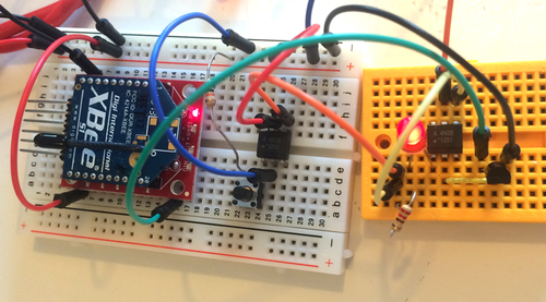
I used a piece of Experiment PCB (Printed Circuit Board) the size of the XBee Module and added all components. Using tiny pieces of wires as jumpers I connected all components as drawn in the diagram. The small size of the board ended up very ambitious, but I managed to get everything on it.
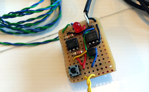
In this version the C1 capacitor and R3 resistor are still missing. The green and blue wires are the signal wires from the dishwasher, black and white are connected to a small 5v power supply (an old Nokia Phone charger) and the yellow wires are connected to the reset button. I soon figured it would be more convenient to make the green and blue wire detachable, so I ended up using a PCB mountable screw connector for this.
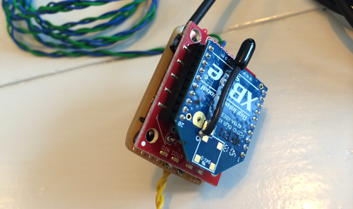
On the back side I mounted a nice red XBee Explorer Regulated shield, which functions as a power regulator and socket for the XBee. Since the XBee is a 3.3v device, and I’m using a 5v power supply, this shield is a necessary and welcome addition. The shield is connected back to back to my PCB with 3 small wires to keep everything compact.
But I’ll be honest with you; after the 3rd modification I had to make, it all became extremely cramped, so eventually I ended up mounting the two prints side by side. Let’s keep this our little secret, Okay?
Using the test button (BTN-TEST in the diagram), I checked if everything worked as expected. I was able to turn on LED1 and the reset button allowed me to turn it off. After mounting the XBee Module in it’s socket, I even managed to receive the signal on my Mac using another XBee device. So it was time for the real test!
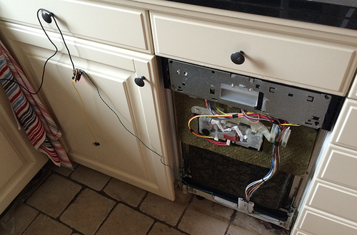
I safely disconnected the power from the dishwasher, connected the green and blue wires to the appropriate connections on the dishwashers computer board, crossed my fingers and started the first test dishes. It worked! After 15 minutes the LED turned on and my Mac got it’s first virtual scream of the silenced vocal cords of hell.
The second test run (long program including multiple waterpump runs) showed the need for the C1 capacitor. Luckily this issue was solved easily. Mounting the PCB and Reset Button below the Dishwasher took me an other 30 minutes …
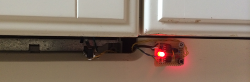
… but after that was done, I could stow away my tools and start programming.
Annoying Dishwasher: The from XBee to Mirror