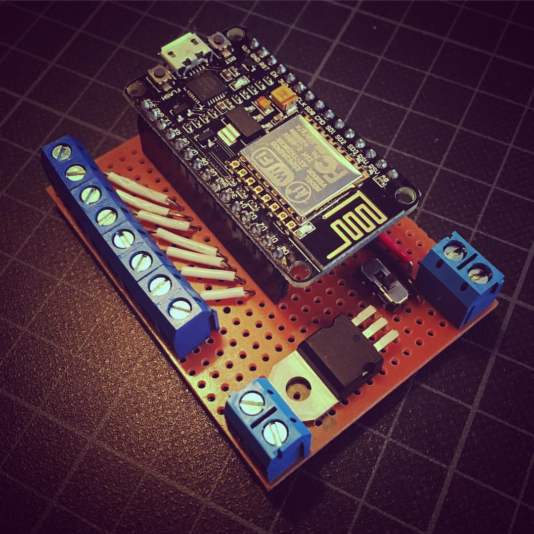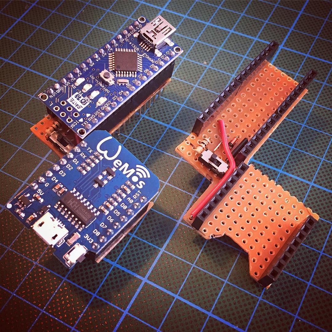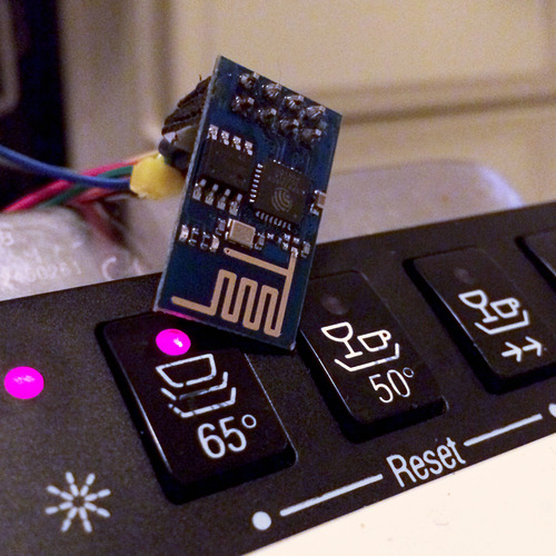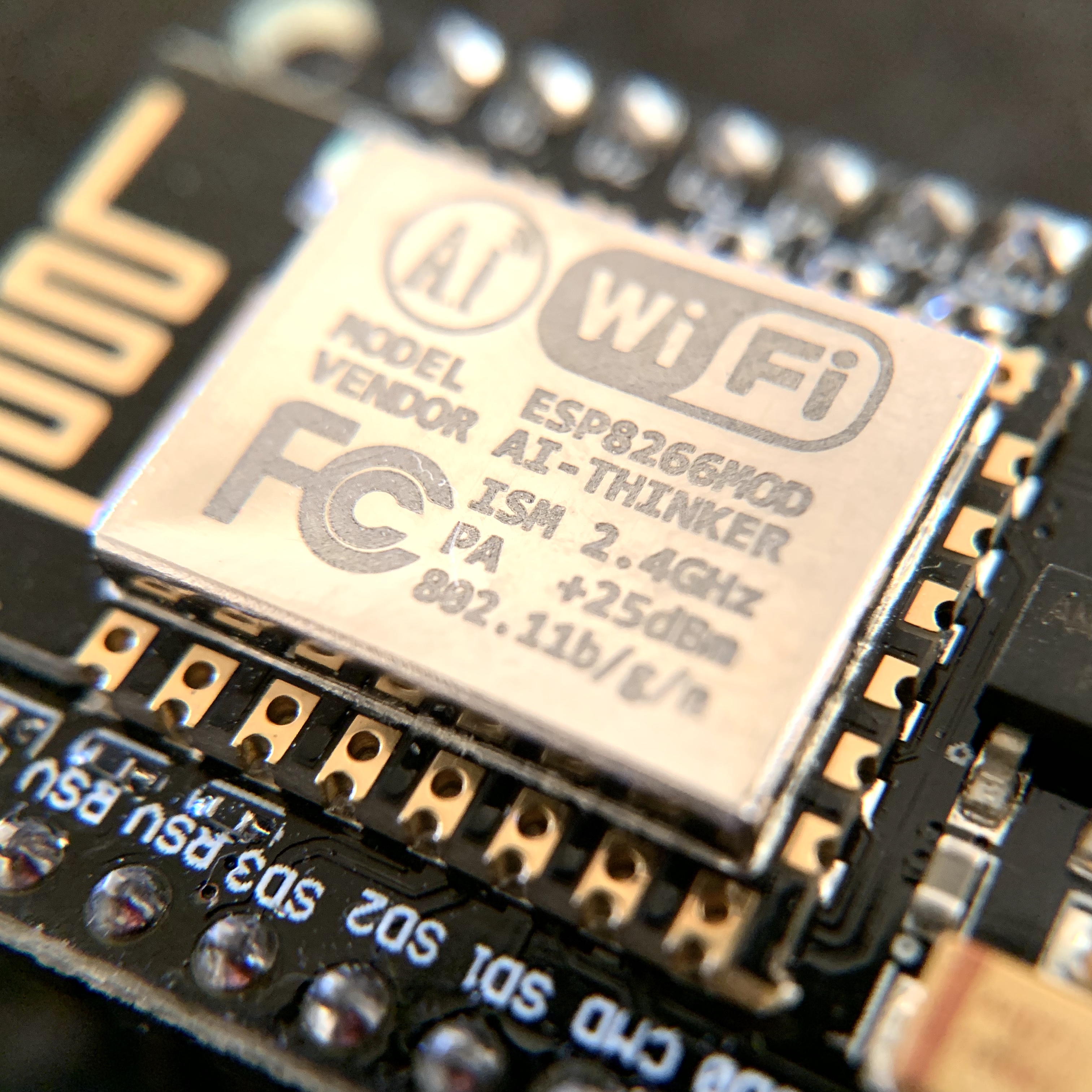
With the new hardware ready, I continue to rebuild my Home Sensor system. Last week I replaced the Raspbery Pi for an ESP8266, this week I’ll be working on the new protocol my Home Sensor will be using.
HomeSensor: New brains for my Alarm
As the backend / protocol for my Home Sensor I’ll be using MQTT. The MQ Telemetry Transport protocol. And while abbreviations often indicate very technical difficult techniques, the MQTT protocol turned out to be the absolute opposite. It is EXTREMELY easy to understand. And more important: easy to use.

The official MQTT site describes the protocol as follows:
MQTT is a machine-to-machine (M2M)/“Internet of Things” connectivity protocol. It was designed as an extremely lightweight publish/subscribe messaging transport. It is useful for connections with remote locations where a small code footprint is required and/or network bandwidth is at a premium. For example, it has been used in sensors communicating to a broker via satellite link, over occasional dial-up connections with healthcare providers, and in a range of home automation and small device scenarios. It is also ideal for mobile applications because of its small size, low power usage, minimised data packets, and efficient distribution of information to one or many receivers.
To summarize it’s basic usage:
- A broker is responsible for receiving and sending all messages. A broker can be open source software running on your computer, server or Raspberry Pi. Or a commercial broker available in the cloud.
- A client can subscribe to specific channels. Channels are identified by using topics. A topic is a string, which is used by the broker to filter messages for each connected client. A topic consists of one or more topic levels. Each topic level is separated by a forward slash (topic level separator). Wildcards can be used to subscribe to multiple channels at once.
- An (other) client can publish messages to specific channels (topics). Allowing the subscribes to be notified.
Of course, there is a lot more to this. If you want to know more about MQTT, I suggest you check out HiveMQ’s MQTT Essentials. HiveMQ is a enterprise MQTT broker. If you want to use MQTT in an enterprise environment. I suggest you check out their site. But not before you hire me as an overpaid consultant.

If you want to run your own MQTT broker (on your computer, server or Raspberry Pi) check out Mosquitto. Though, for the clarity of this post, I’ll be using the Mosquitto test server. Note that the data sent to this server is visible for anyone connected to their server. So use with caution. I’ll be watching your every step …
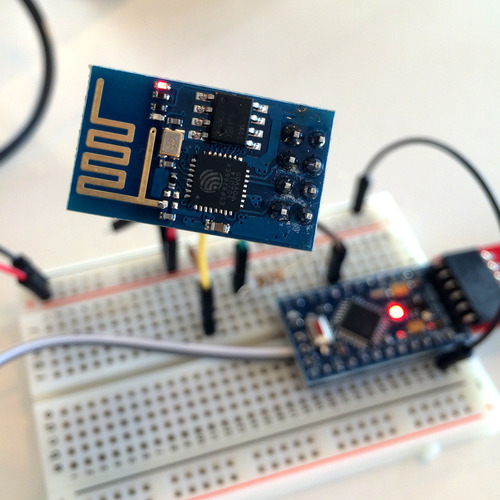
Connecting the ESP8266 to the MQTT server.
There are many open source libraries available allowing you to connect your ESP8266 to a MQTT server. The one I found most stable and complete, is the pubsubclient by Imroy. Note that there are multiple pubsubclient libraries available, so make sure you download the one by Imroy. After installing this library to your Arduino IDE, It’s time to start coding …
First off, lets start by loading the right libraries, and creating some constants and variables:
#include <ESP8266WiFi.h>
#include <PubSubClient.h>

#define WLAN_SSID       "YOUR_NETWORK_SSID"
#define WLAN_PASS       "YOUR_NETWORK_PASSWORD"

WiFiClient client;
PubSubClient mqtt(client, "test.mosquitto.org", 1883);

#define SENSOR_COUNT 5
#define DEVICE_NAME "alarm"

byte sensorPins[SENSOR_COUNT] = {5, 4, 14, 12, 13}; // The pins to which the sensors are connected.
boolean sensorStates[SENSOR_COUNT] = {1, 1, 1, 1, 1};
String deviceName = DEVICE_NAME;
String sensorNames[SENSOR_COUNT] = {"hallway","bedroom","livingroom","kidsroom","door"};
With the libraries loaded, and the variables created, let’s define the setup routine:
void setup() {

    // the the pinmode for all used pins to INPUT_PULLUP
    for (byte i = 0; i < SENSOR_COUNT; i++) {
        byte pin = sensorPins[i];
        pinMode(pin, INPUT_PULLUP);
    }

    // Initiate the serial connection for debugging.
    Serial.begin(115200);
    delay(10);

    Serial.println("Starting ...");
}
Next up, let’s define the main runloop in the loop() method.
void loop() {

    // Check if the Wifi is connected, if not, call the WiFi_connect() method.
    if (WiFi.status() != WL_CONNECTED) {
        WiFi_connect();
    }

    // Check if there is a connection with the MQTT server, if not, call the MQTT_connect() method.
    if (!mqtt.connected()) {
        Serial.println("MQTT Disconnected!");
        MQTT_connect();
    }

    // Call the loop method, to periodically ping the server to keep the connection alive.
    mqtt.loop();

    // Loop thru all the sensors defined at the start.
    for (byte i = 0; i < SENSOR_COUNT; i++) {

        // Create some helper variables.
        byte pin = sensorPins[i];
        boolean pinState = digitalRead(pin);
        boolean lastPinState =  sensorStates[i];
        String sensorName = sensorNames[i];

        // Check if the state for the current pin has changed.
        if (pinState != lastPinState) {

            // Define a string with the topic to which we want to post the new state to ...
            // and convert it into a char * array which we need for the pubsubclient.
            String feedNameString =  String("/device/" + deviceName + "/sensor/" + sensorName);
            char topic[feedNameString.length() + 1];
            feedNameString.toCharArray(topic, feedNameString.length() + 1);

            // Output the new state to the serial for debugging.
            Serial.print("New state for sensor ");
            Serial.print(topic);
            Serial.print(": ");
            Serial.print(pinState);

            // Publish the new state to the MQTT server.
            // The message is sent as a retained message to always
            // have the last state available on the broker.
            // The QoS is set to 1, to make sure the delivery
            // of the mseeage to the broker is guaranteed.
            if (mqtt.publish(MQTT::Publish(topic, pinState ? "1" : "0").set_retain().set_qos(1).set_dup())) {
                Serial.println(F(" ... Published!"));
            } else {
                Serial.println(F(" ... MQTT PUBLISH FAILED!"));
            }

            // Store the new pinstate in the pinStates array.
            sensorStates[i] = pinState;
        }
    }

    // Wait 50 miliseconds before we repeat the runloop.
    delay(50);
}
As you can see, the WiFi_connect() and MQTT_connect() methods were used to make a Wifi and MQTT connection. To be able to use these to methods, they of course need to be defined …
void WiFi_connect() {
    // Print some debuggin info to the serial terminal.
    Serial.println(); Serial.println();
    Serial.print("Connecting to ");
    Serial.print(WLAN_SSID);
    Serial.print(" ");

    // Connect to the WiFi netwerk using the previously defined SSID and Password.
    WiFi.begin(WLAN_SSID, WLAN_PASS);
    while (WiFi.status() != WL_CONNECTED) {
        // If there is no connection. Wait half a second before checking again.
        delay(500);
        Serial.print(".");
    }
    Serial.println();

    // After the connection is established, print the IP-adres to the serial terminal for debugging.
    Serial.print("WiFi connected! - ");
    Serial.print("IP address: ");
    Serial.println(WiFi.localIP());
}

void MQTT_connect() {
    // Define a string with the topic to which we want to post the connection state of this device to ...
    // and convert it into a char * array which we need for the pubsubclient.
    String feedNameString =  String("/device/" + deviceName + "/connected");
    char topic[feedNameString.length() + 1];
    feedNameString.toCharArray(topic, feedNameString.length() + 1);

    // As long as there is no active MQTT connection ...
    while (!mqtt.connected()) {
        Serial.print("Attempting MQTT connection ... ");

        // Try to connect to the MQTT broker.
        // As the 'will' we set the topic and connection state to 0.
        // This means that is if the connection is dropped,
        // the broker will publish the connection state to the defined topic.
        if (mqtt.connect(MQTT::Connect(DEVICE_NAME).set_will(topic, "0", 1, true))) {
            Serial.println("Connected!");

            // After the connection is established, publish a new connection state.
            mqtt.publish(MQTT::Publish(topic, "1").set_retain().set_qos(1));

        } else {

            // Wait half a second before trying again.
            Serial.println("Failed! - Try again in half a second.");
            delay(500);
        }
    }
}
And that’s all the ESP8266 needs to publish the sensor states to the MQTT broker. To check if it works, let’s subscribe to the defined topics, and see if we receive notifications when the state of the sensors change. Conveniently, the installer of the Mosquitto broker includes a handy tool to subscribe to topics on the commandline: mosquitto_sub
To subscribe to the topics we want to check, I use the following command:
mosquitto_sub -h test.mosquitto.org -t /device/alarm/# -v
- -h test.mosquitto.org defines the broker we want to connect to.
- -t /device/alarm/# we want to subscribe to. The # is a multilevel wildcard.
- -v runs mosquitto_sub in verbose mode so that it also displays the topics when a new message arrives.
If I run the command, and start running though my house, the result is as follows:
/device/alarm/connected 1
/device/alarm/sensor/livingroom 1
/device/alarm/sensor/door 0
/device/alarm/sensor/hallway 0
/device/alarm/sensor/bedroom 0
/device/alarm/sensor/kidsroom 0
/device/alarm/sensor/livingroom 0
/device/alarm/sensor/hallway 1
/device/alarm/sensor/hallway 0
/device/alarm/sensor/bedroom 1
/device/alarm/sensor/bedroom 0
/device/alarm/sensor/hallway 1
/device/alarm/sensor/hallway 0
/device/alarm/sensor/livingroom 1
...
It works! Awesome!

And with the new alarm sensor up and running, the possibilities to use this data in other applications are unlimited. Want to connect to an MQTT server to subscribe to your ESP8266 messages? Check out the following libraries:
- MQTT.js - A Node.js library
- MQTT-Client-Framework - An Objective-C native MQTT Framework (also usable in Swift).
- phpMQTT - A simple php class to connect/publish/subscribe to a MQTT broker.
- Paho - A java MQTT client library.
- Want more? Check out this extensive list.
Next thing on my todo list? Fix the door sensor. I’ve got the solution for this, but that will be my cliffhanger for now.
Let me know what you’ll be using MQTT for in the comments down below. Happy MQTT'ing!
HomeSensor: Keep an eye on the door!