
A Tiny Success: Flashing the USBasp
Two weeks ago I posted about my experiment with the ATTiny10. A 12Mhz 8-bit micro controller small enough to be confused with an obese ant. Unfortunately I didn’t succeed in programming this tiny guy, so this week I continue my small scale flashing quest.
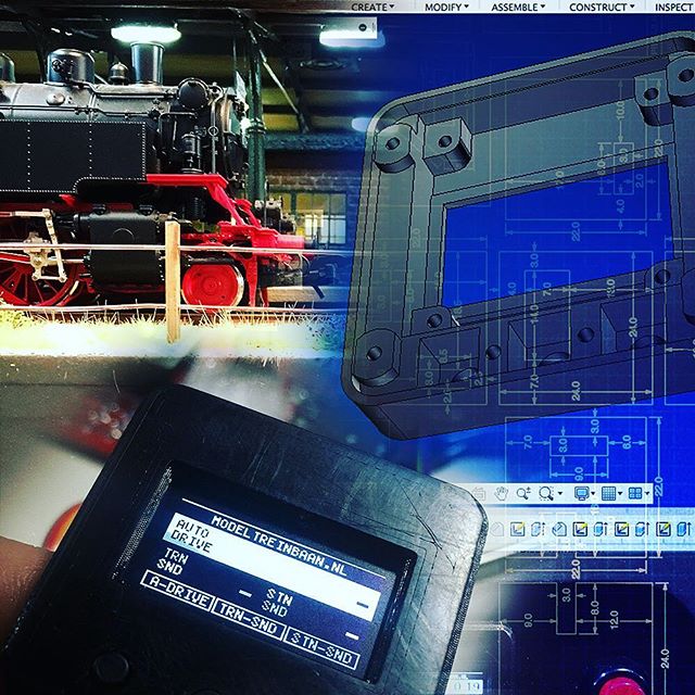
Train Automator:
Wrapping it up!
Over the course of the last few weeks I’ve been building the Arduino powered Model Train Automator. I’m sure my dad would like to start using it, so let’s wrap this project up!
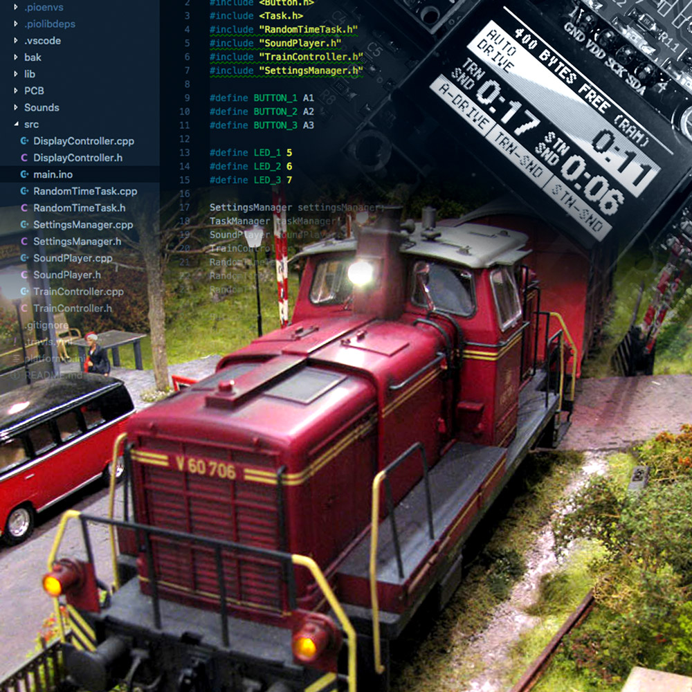
Train Automator:
Writing the Software
After finishing the electronics it is time to work on the software. Since the train automator runs on an Arduino Nano, it’s time to fire up Visual Studio Code and start typing some C++.
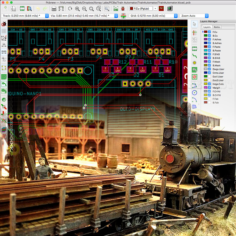
Train Automator:
Designing the PCB
Since the prototype turned out to be a success, it is time to work on a more professional solution: a custom PCB. Of course I don’t just slap an Arduino and a MAX485 IC on a board and call it a day. I use this opportunity to add some nifty features to the custom board. You know, just to impress my dad.
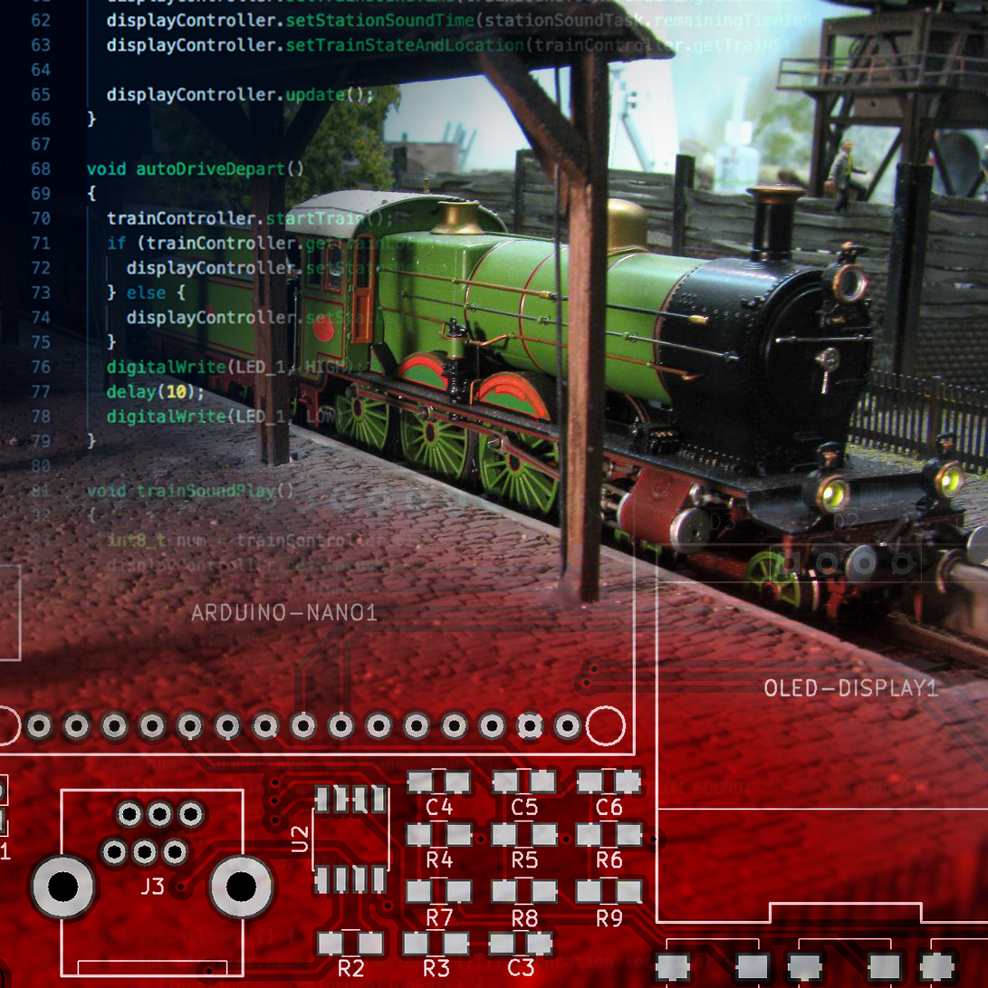
Train Automator:
Prototyping
As my regular readers know, my dad is an avid Model Train hobbist. And altough my interest is more on the digital side of electronics, every now and then our hobbies meet. After my recent Arduino powered analog clock project, I once again will work on a project for my dad: Let’s make his trains Arduino powered!
What time is it? Father's Day!
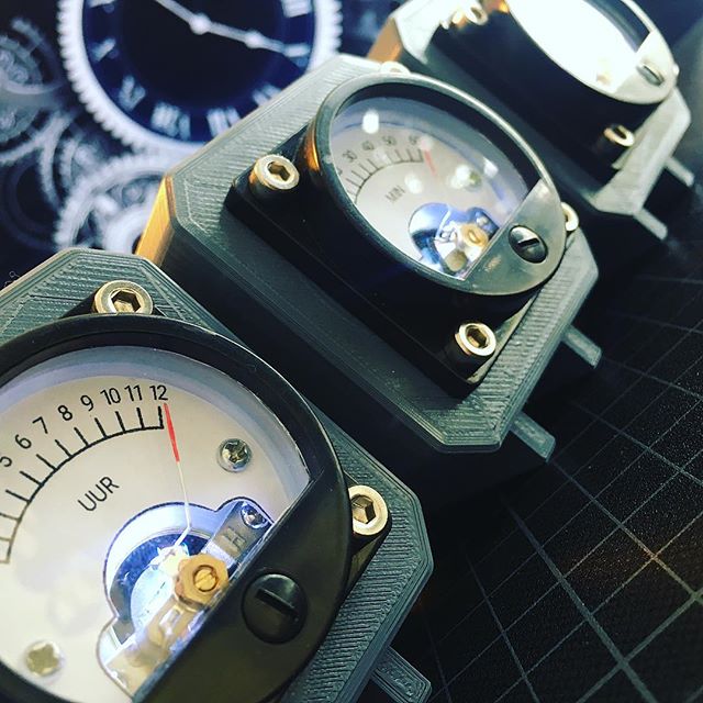
My technical enthusiasm is probably 99% inherited from my dad. So whenever I come across something fascinating, he is usually the first person to forward the link to. A little over a year, I came across some really awesome volt meter clocks. And due to his fascination of analog meters, he liked it even more than I did. Wouldn’t it be awesome to make one as a Father’s Day present?

Activity Board:
The Final Touch
It has been almost a year since I started the activity board project. So it is time to wrap it up. As said in the last activity board blog post, the only thing left to do was to finish the interface …
Activity Board:
Bake me some Pi!
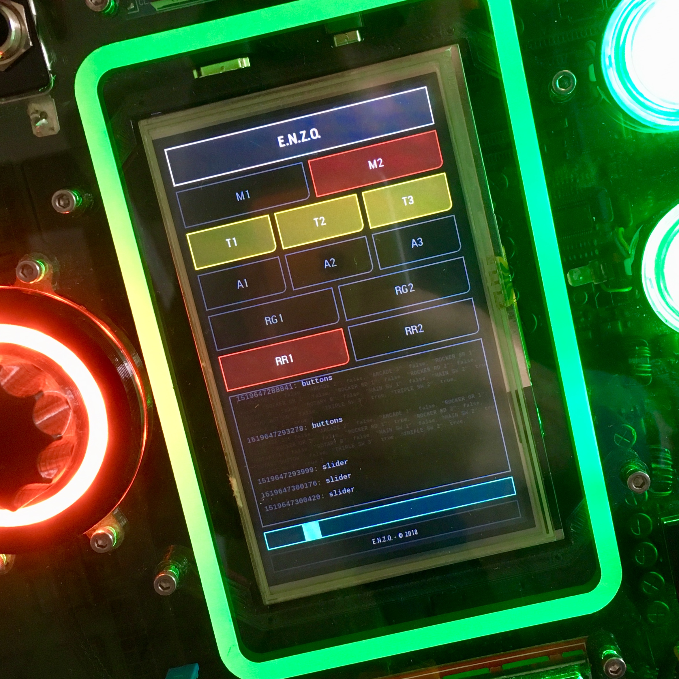
Now that most of the firmware is all set an done, it’s time to start working on the final part of the Activity Board: the Raspberry Pi display interface.

Activity Board:
It's all about the code!
With the activity board controller finally in place and tested. It’s time to throw together the actual firmware. Let’s fire up VSCode!
Activity Board:
Take control!
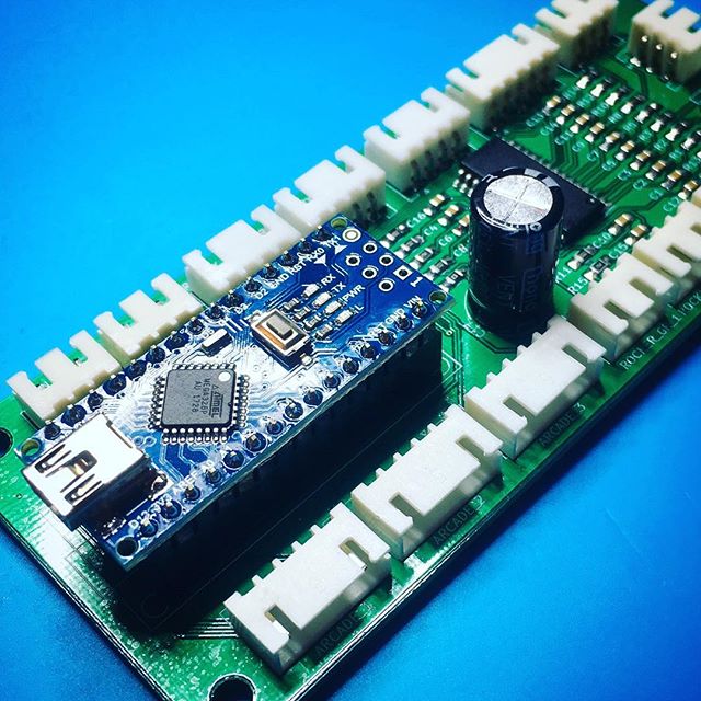
In my last activity board blog post I finished the final part of the control panel. It is time to start working on the electronics. Or to use a bit more exciting terminology: it is time to work on the activity board controller!
Activity Board:
Assembling the panel
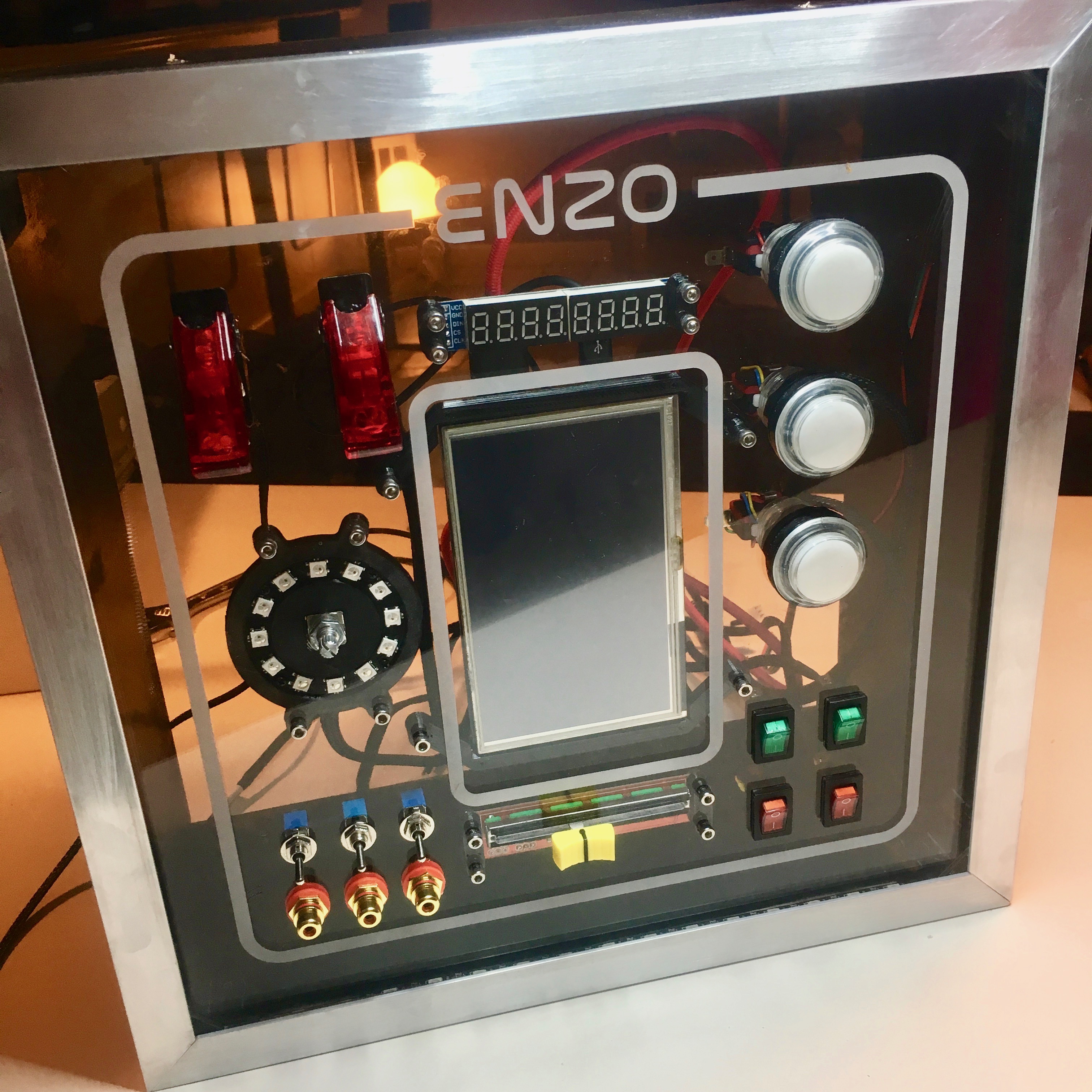
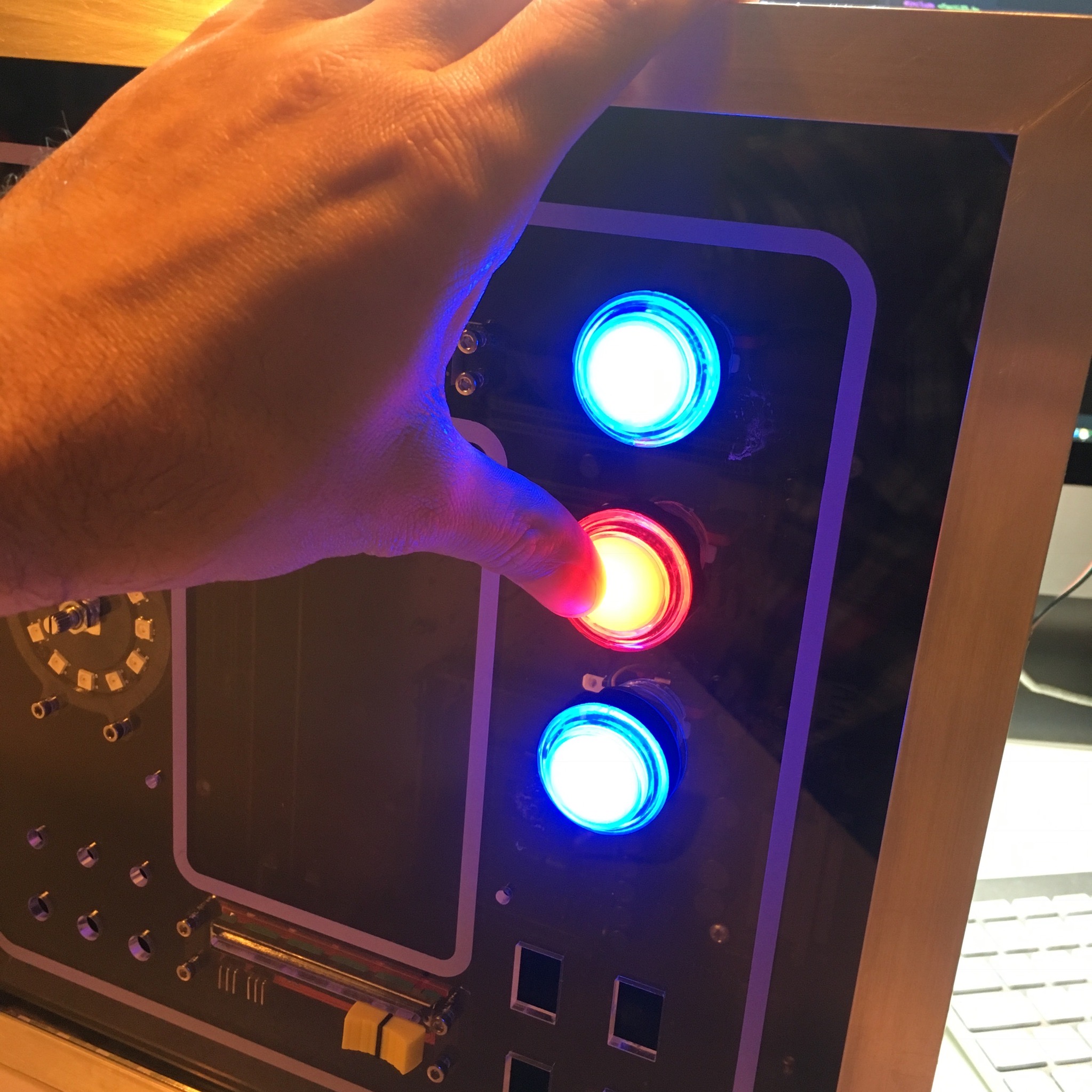
After a succesful intergration of the push buttons it is time to wrap up the front panel. With 9 switches, 3 buttons, 2 displays, 1 slide pot, 1 rotary encoder and a lot of LEDs, this includes a lot of wiring.
Activity Board:
Push the button!
Now that the activity board casing is done. It’s time to start the wiring of all the components. A tedious job which I take way too serious.
Electrocard:
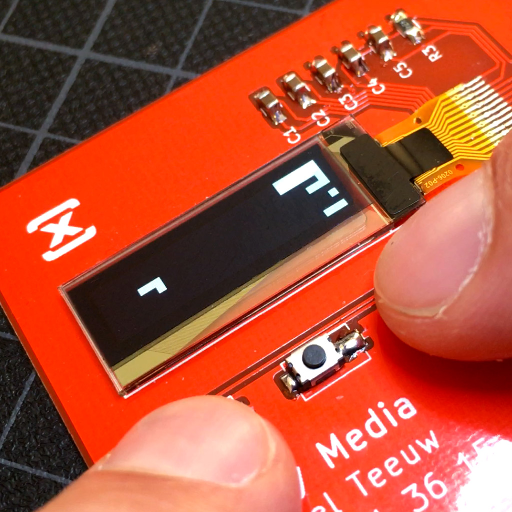
Writing The Software
Now that the hardware part of my Electrocard is done, it’s time to start working on the software side of my electronic business card.
Electrocard:
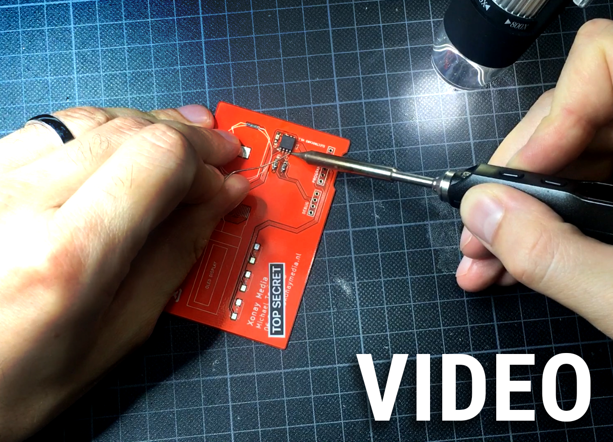
Soldering
After my beautiful shiny new PCB business cards arrived, the fun could begin. Time to start soldering! And since a blog post about soldering isn’t the most exciting, I decided to make a video showing the full process.
Electrocard:
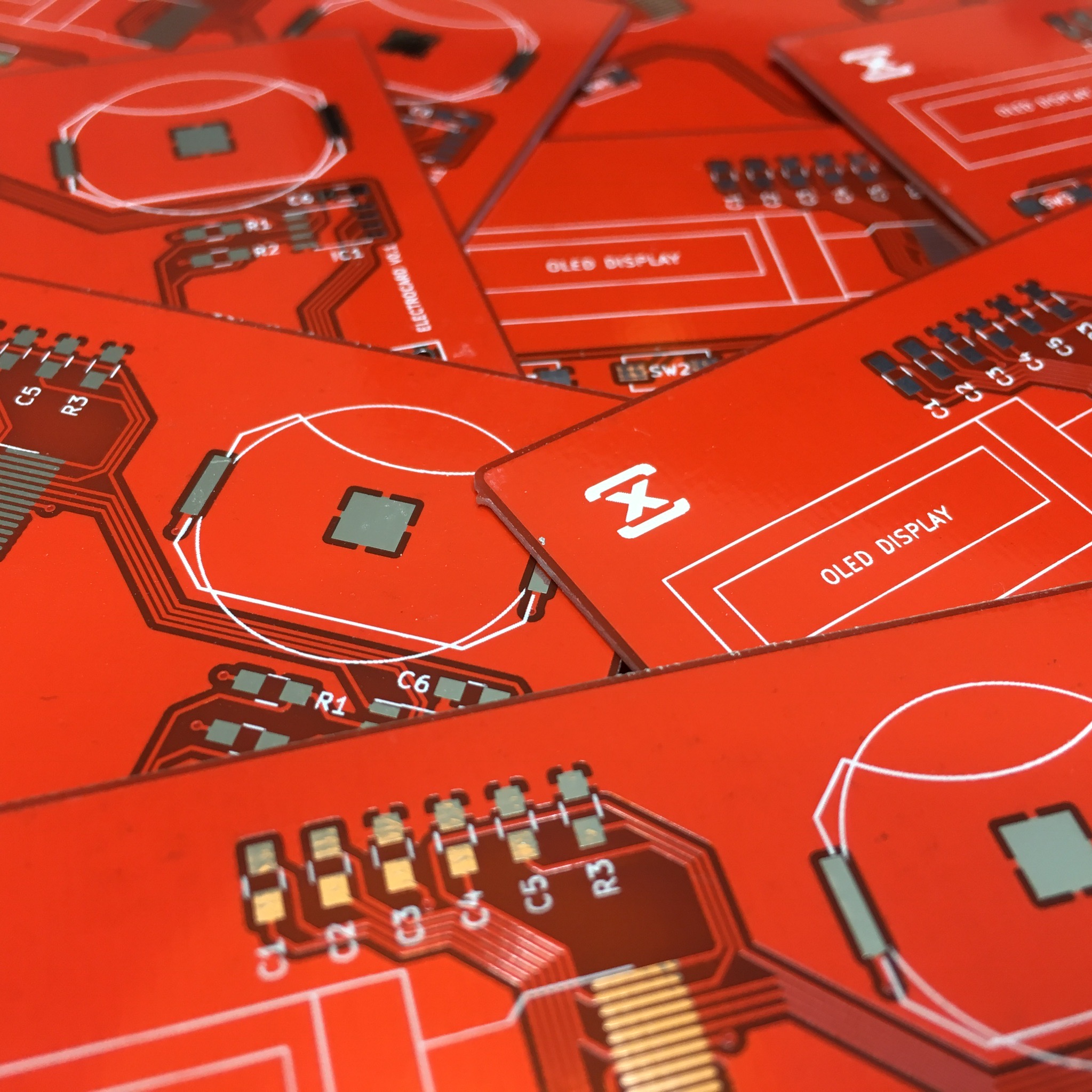
The Design
Ever since I have my own company I wanted to have a PCB business card. Of course I wouldn’t be the first, but it would definitely give a nice touch to my company’s identity. And since I wanted to give KiCad a good try anyway, why not go for it?
Automatic Curtains:
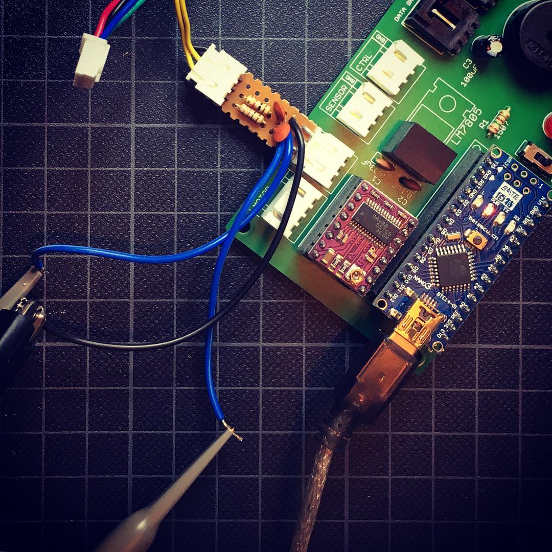
Debugging my curtains.
Ever since I’ve finished the first prototype of my Automatic Curtain project one and a half years ago, the curtains have been running without any issues. Unfortunately, that came to an abrupt end this weekend.
The Train Controller
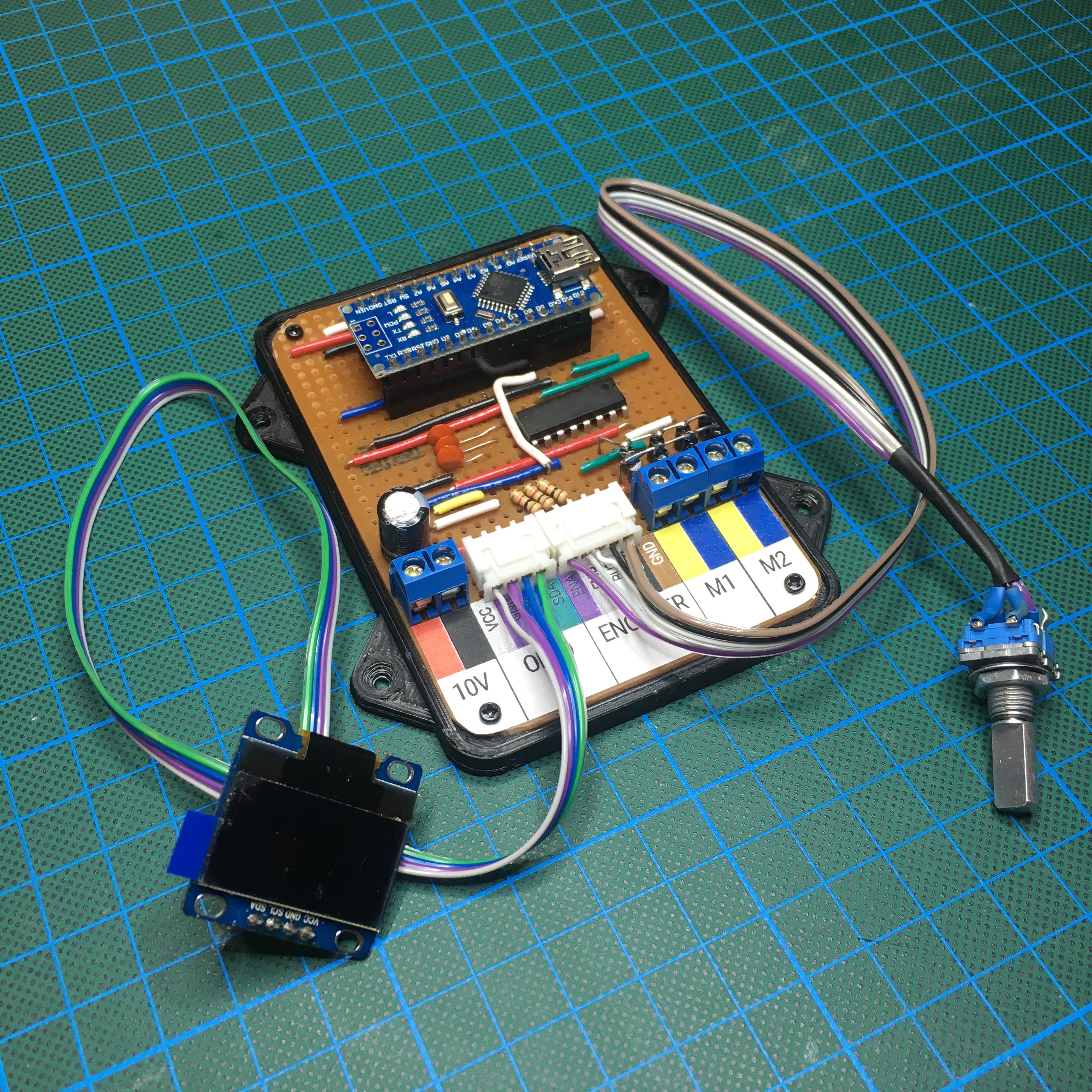
A while ago my dad and I were discussing the best ways to control a small model train. As a seasoned model train enthusiast, he was looking for the best way to control a single track train. As an additional requirement, he wanted to show the trains’ speed on a small display … Challenge accepted!
Activity Board:
Building the Box
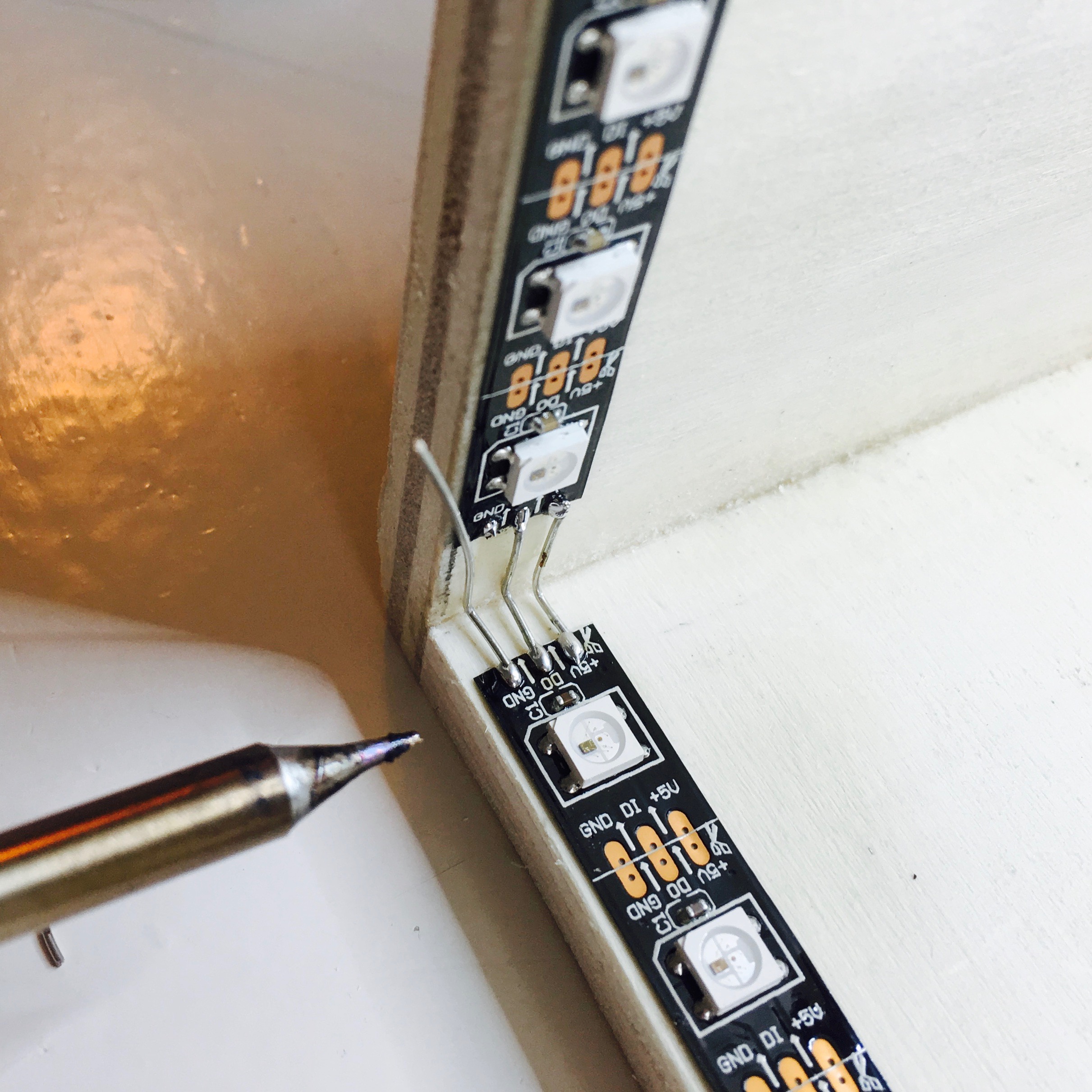
Before I can work on the front panel design of Enzo’s Activity Board, I need to know the exact dimensions. This can be figured out either by using some math, or by simply just measuring it. I choose the latter, but this means I first need to build the box that holds everything in place …
Activity Board:
Enzo's Control Room
With all of my projects that include one or more buttons, I know one thing for sure. The buttons will be extensively tested by my 1,5 year old tinkerer Enzo. My Automatic curtains need to open and closed more than a few times a day, and my robot arm’s test buttons are being pressed repeatedly even while it isn’t powered on. I think the message is clear: he wants his own buttons!
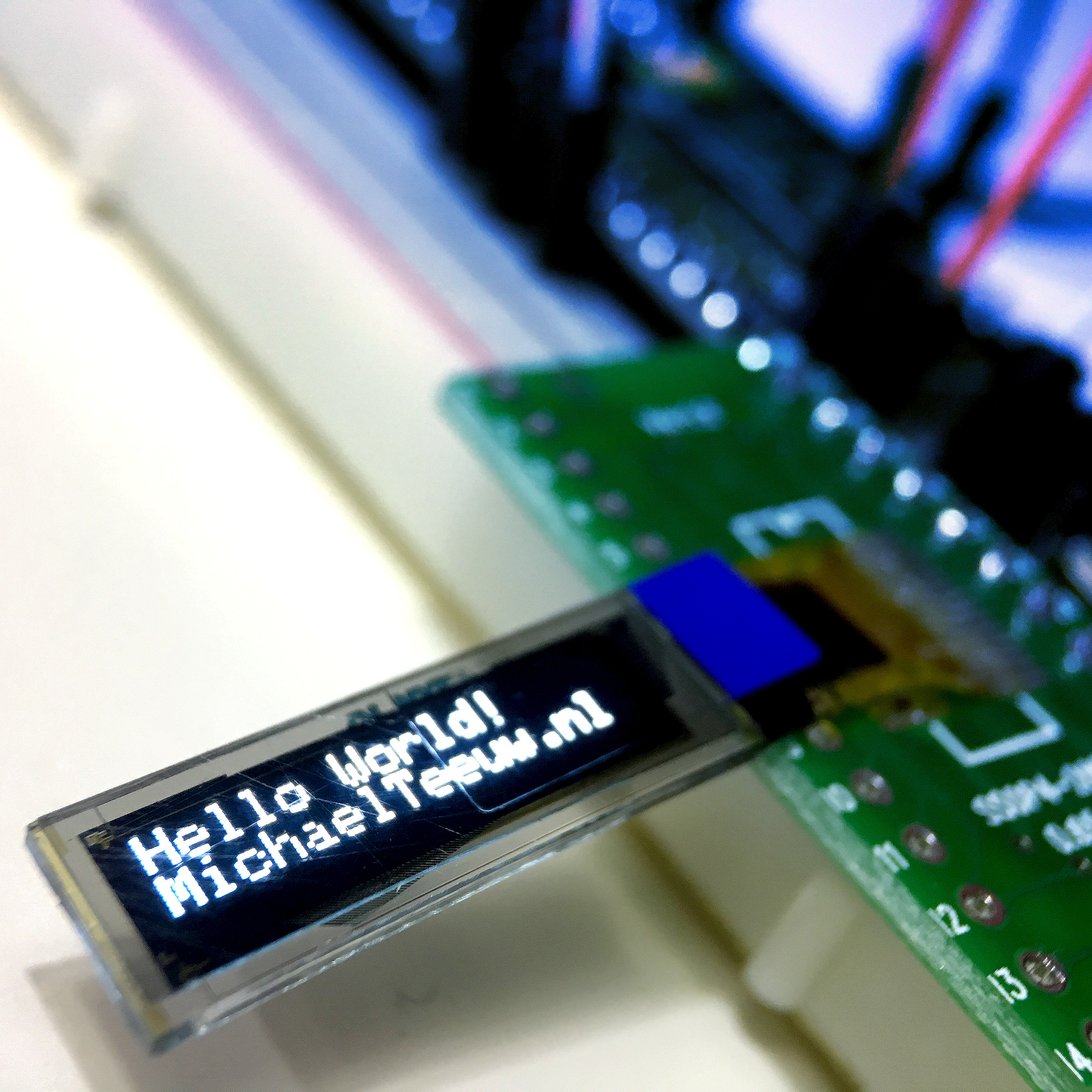
Trying out a Barebone OLED display
If you you are a tinkerer that likes to play around with Arduino’s and electronics, you’ve probably played around with a 4 pin I2C OLED display more than once. To step up my game, I thought it would be fun to give myself a little challenge and try out a barebone OLED screen without the convenient breakout board.
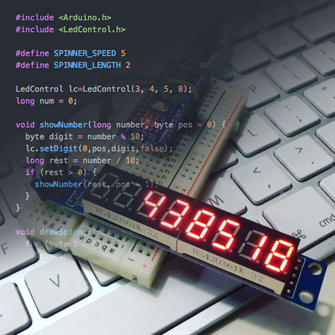
The Recursive LedControl Counter
2 weeks ago I posted a small clip on my Instagram which showed a MAX7219 counter demo. Using this 8 digit, 7 segment display is pretty straight forward, but some people asked me how I printed the incremetal counter, since the MAX7219 LedControl library only allows you to print one digit at a time …
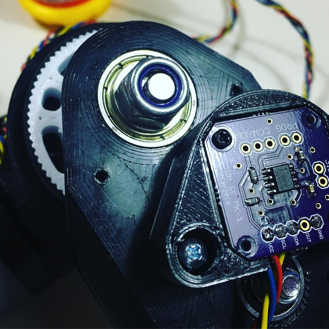
Robotic Arm:
Give me some feedback!
To improve my robot arm’s accuracy, I wanted to add an absolute position feedback mechanism. Aside from it’s accuracy, it would also prevent the need for end stops. But most importantly, it would give me a reason to play with a AS5600 12-bit on-axis magnetic rotary position sensor.
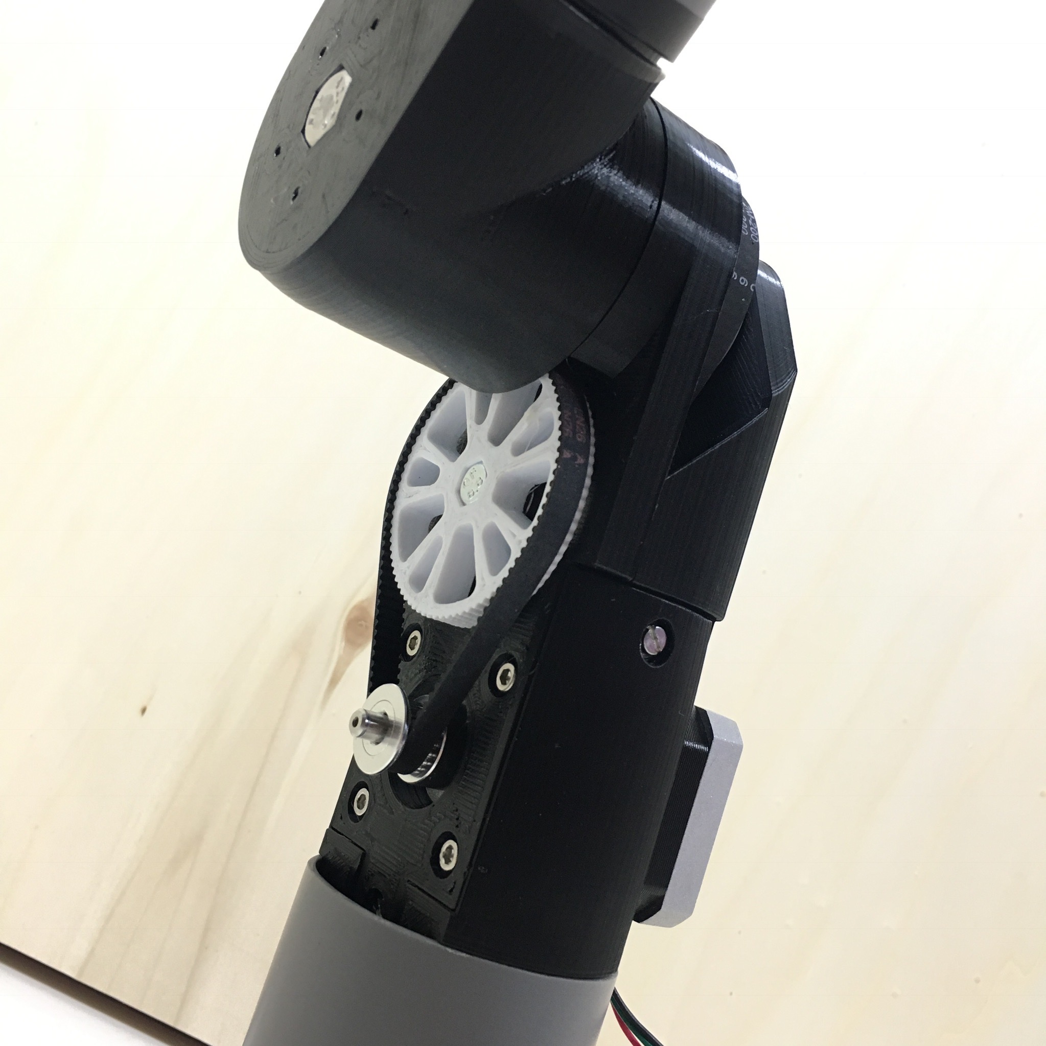
Robotic Arm:
Pulley & Belt Transmission
Admittedly, building a robot arm joint transmission is way more difficult than I expected. But where’s the fun in a simple project? In my last post, I explained why a geared transmission doesn’t work. This week I’ll try a new approach.
Quiz Time:
Quiz Time. Again!
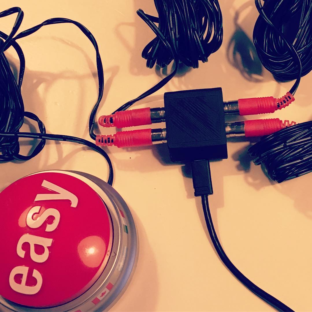
A few years ago I introduced a new Christmas Dinner tradition: we play a quiz to test the attendees knowledge of the news facts of the past year. How many gold medals did we win during the Olypics? On what day did Trump win the election? And who won the Eurovision Song Contest? This year I improved the Quiz experience with the help of some maker magic …