A little over 2 years ago I worked on a project in which I connected my alarm’s sensors to the web using my first Raspberry Pi. And while it still didn’t help me to lower the crime rate in my peaceful village, it turned out to be a very handy toy. Unfortunately, the system had some minor flaws, so it’s time to work on an improved solution.
HomeSensor: Protecting my Man Cave

The original system was based on a custom developed node.js system with socket connections which allowed my to connect multiple devices to a notification system and tailor made “home sensor” app. Unfortunately, the Pi’s OS has the tendency to die when the file system crashes during power outages.
Additionally, I’d like to move to a more open en proven communication standard. Allowing me to connect multiple future projects such as my automatic curtains. So no more full fledged unix controllers, no more node.js, no more custom built communication protocols. Let’s start from scratch!
You mean, you can’t get that Raspberry Pi back up and running, huh? And and now you’re sitting there with a non functional Alarm … right?
~ My conscience.
Selecting the brains!
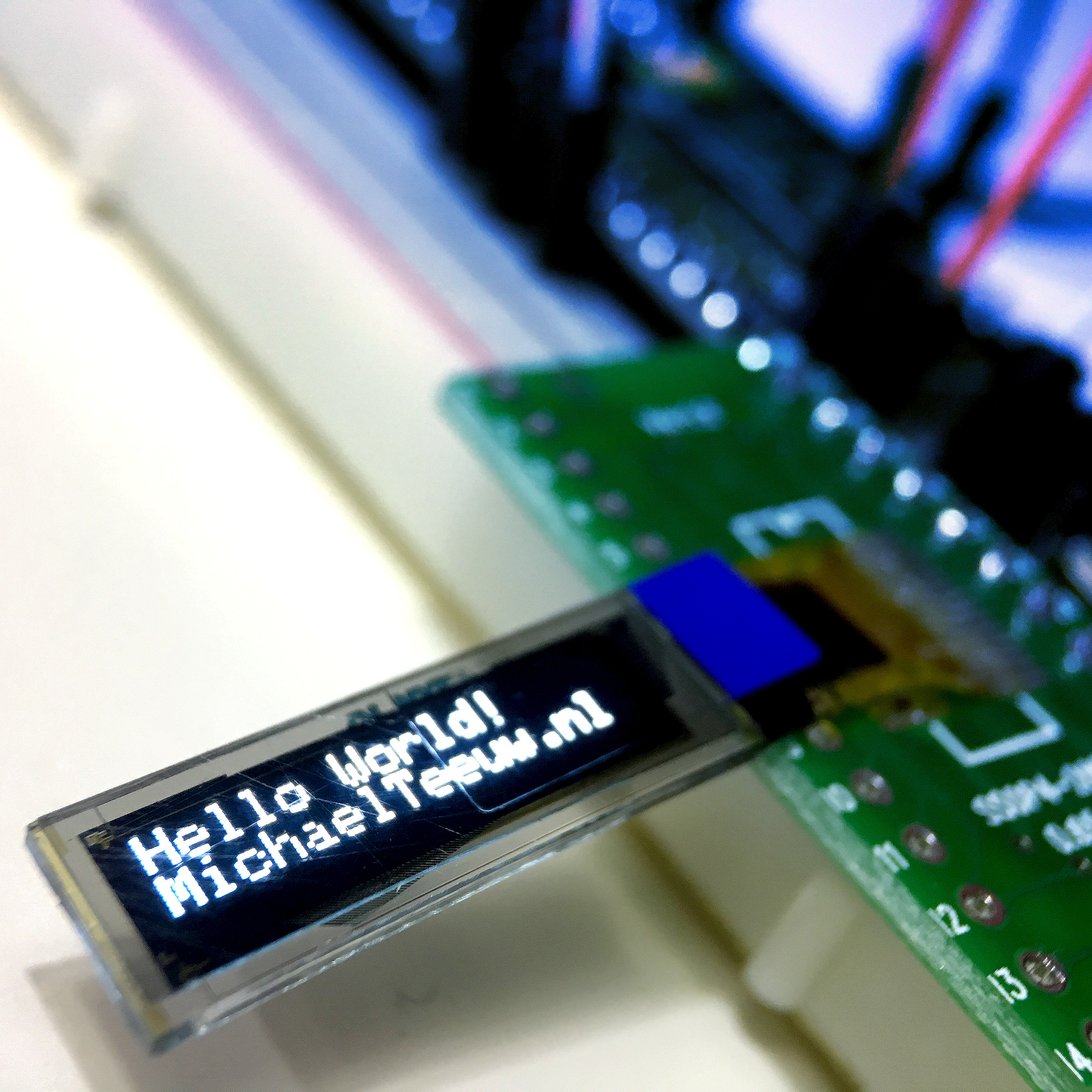
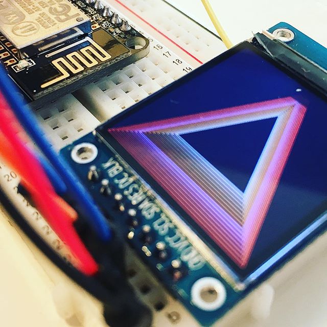
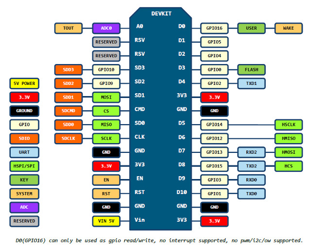
Since the main issue of my current solution was the operating system and the file system. The logic choice is to switch to a micro controller. And since we need connectivity, an ESP8266 NodeMCU module is a simple choice. This $4,- module features a 80Mhz micro controller, has on board wifi and offers the convenience of an on board USB to Serial controller for easy programming and debugging. And with digital 13 GPIO connections, this little fellow offers me more IO than needed. These nicely packaged modules are marketed as NodeMCU for use with the LUA language, but of course, you can flash it with any type of firmware you like, including the code you write using the Arduino IDE. Actually, The best part of the ESP8266 is that it can be programmed using the Arduino IDE. Allowing you to use (most of) the Arduino libraries and examples!

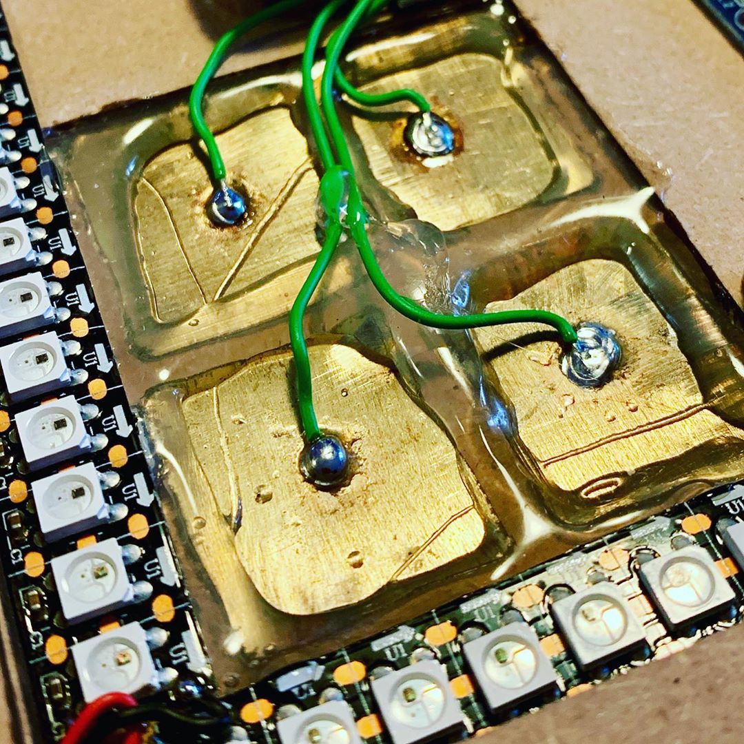
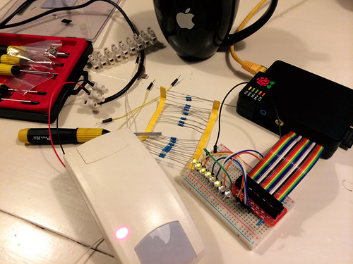
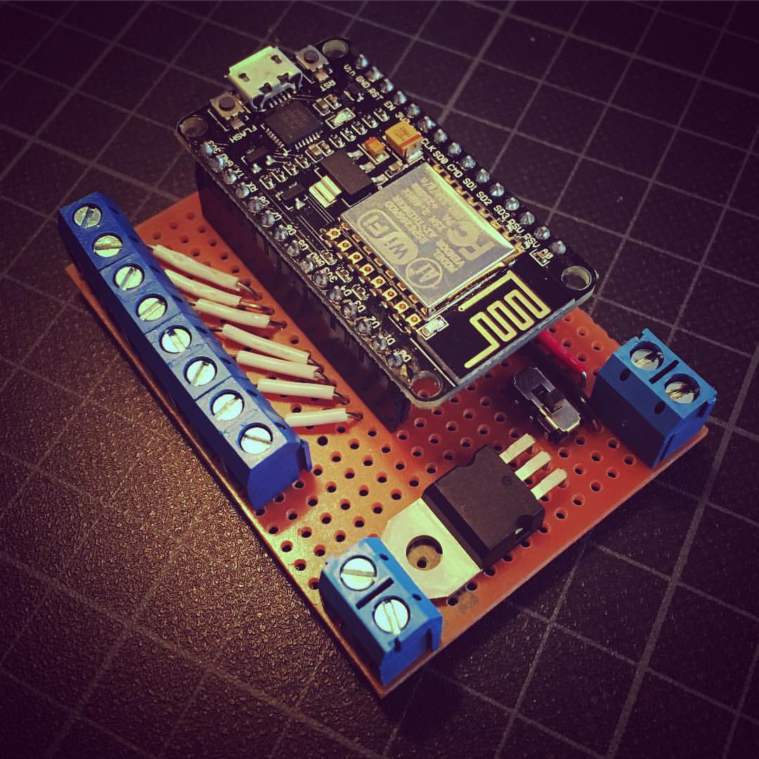
Although the ESP8266 is a 3v3 chip, the module has an onboard power regulator allowing it to handle 5 volt. My alarm sensors need 12 volt and are powered using an old 12v external harddrive power brick. To prevent the need of two power sources, a simple LM7805 linear voltage regulator is used to lower the 12 volts to 5 volts. (I’m trowing in some IC type numbers here to improve the technicality of this article. Just read on …) For my convinience, I added this regulator to some proto-board together with female header pins (holding the ESP8266 module) and screw terminals which allow me to connect the alarm sensors.
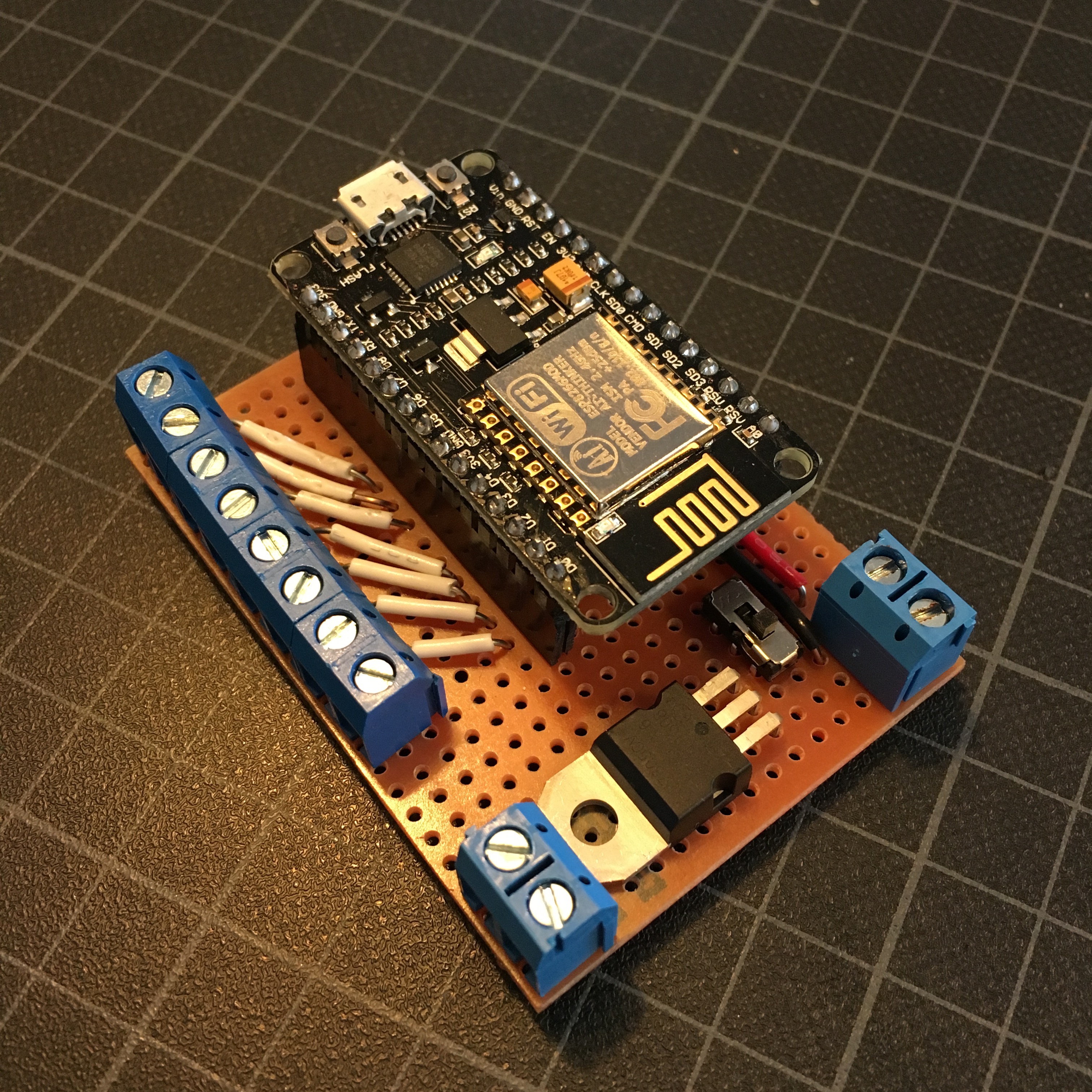
Besides the screw terminal which feed the power to the sensors, and connect the board to the power brick, all the terminals are connected to the ESP8266’s first 8 digital GPIO pins. After some testing, trail and error, I discovered I should not use GPIO16, GPIO0 and GPIO2, since these pins are used during the flashing procedure, and could prevent the module from booting up after a power failure. Luckily, this left me with 5 usable connections, which is enough for my 5 alarm sensors.
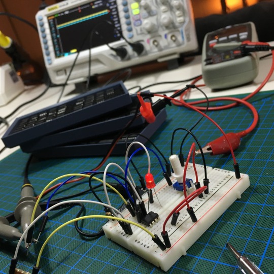
After some soldering, installing the right USB to UART Bridge drivers and adding the ESP8266 board to the Arduino IDE, it was time for some programming.
Testing the connections.
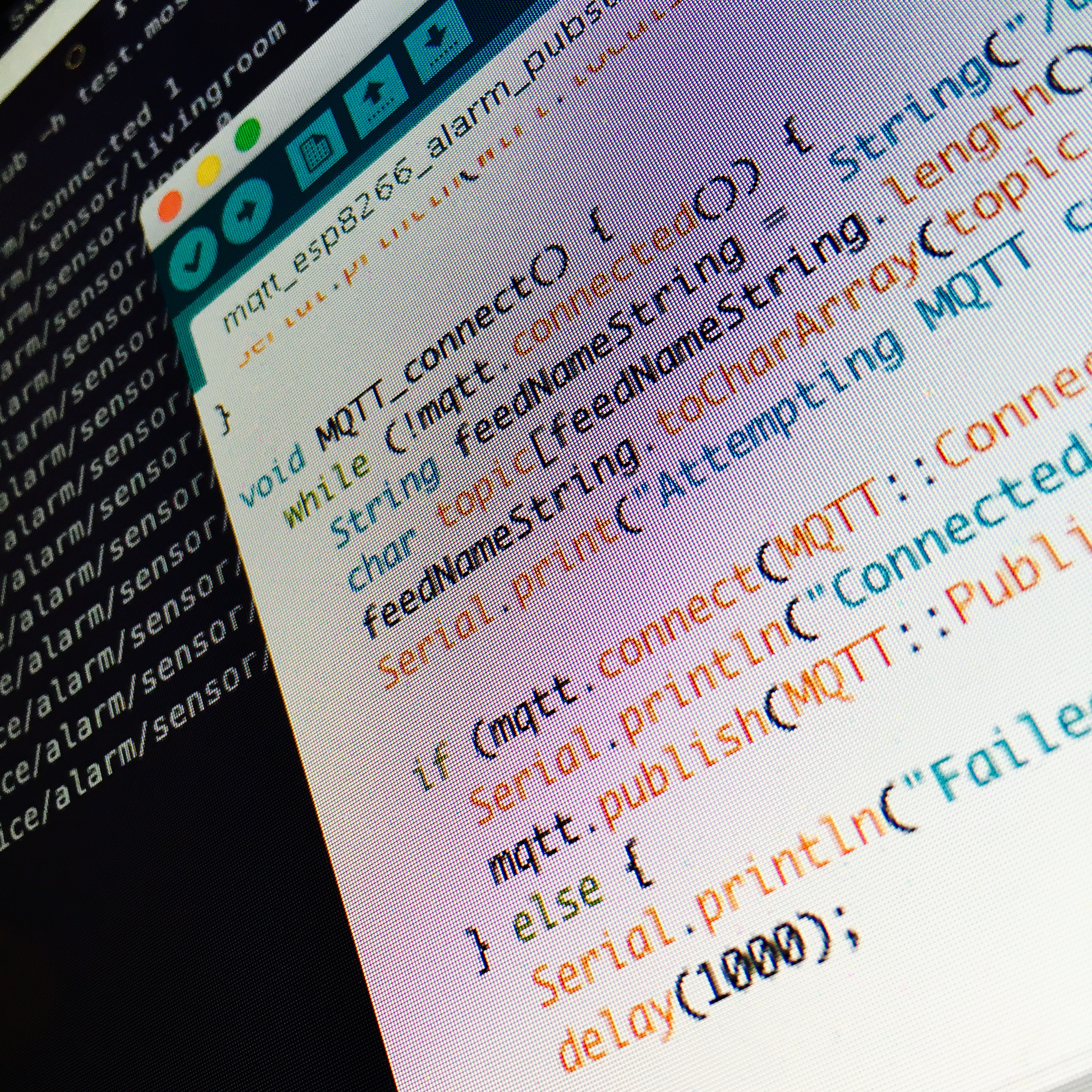
To check if the connected alarm sensors work as expected. I wrote a small debug sketch which outputs the sensor states to the serial console if that change.
#define SENSOR_COUNT 5

byte sensorPins[SENSOR_COUNT] = { 5, 4, 14, 12, 13};
String sensorNames[SENSOR_COUNT] = {"hallway", "bedroom", "livingroom", "kidsroom", "door"};
boolean sensorStates[SENSOR_COUNT] = {1, 1, 1, 1, 1};

void setup() {
    for (byte i = 0; i < SENSOR_COUNT; i++) {
        byte pin = sensorPins[i];
        pinMode(pin, INPUT_PULLUP);
    }

    Serial.begin(115200);
}

void loop() {
    for (byte i = 0; i < SENSOR_COUNT; i++) {
        byte pin = sensorPins[i];
        boolean pinState = digitalRead(pin);
        boolean lastPinState =  sensorStates[i];
        String sensorName = sensorNames[i];

        if (pinState != lastPinState) {
            Serial.print("New state for sensor ");
            Serial.print(sensorName);
            Serial.print(": ");
            Serial.println(pinState);

            sensorStates[i] = pinState;
        }
    }

    delay(50);
}
As hoped, the ESP8266 neatly outputted the state changes of (most) my Alarm sensors correctly.
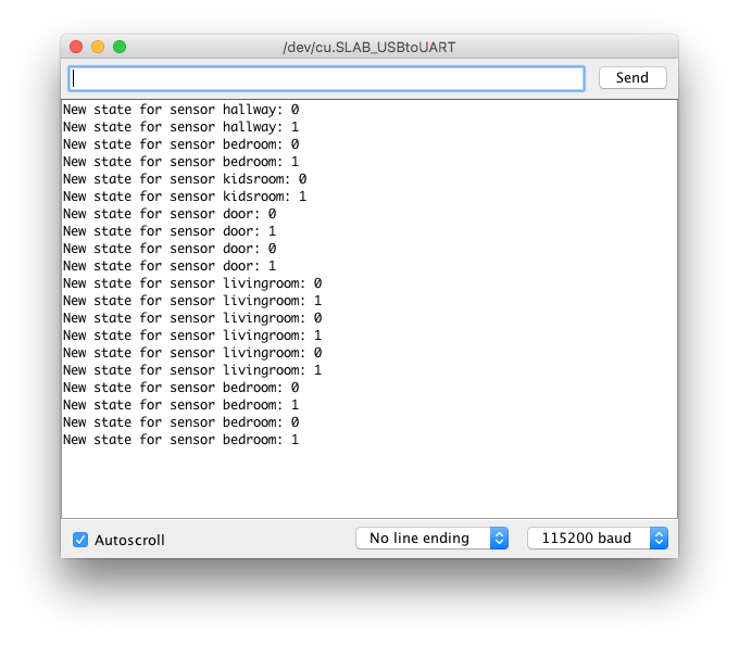
Unfortunately, the door sensor appeared to have some issues, since this isn’t a simple on/off sensor. Instead it turns out it alters between a 5k and 10k resistance depending on the state of the door. A simple solution would be to used the ADC port (analog-to-digital converter) of the ESP8266 to measure the resistance, but of course. There are many other solutions (like using an op-amp or optocoupler), so I leave this issue open to be fixed at a later stage.
(Yeah … rrrigghtt…)
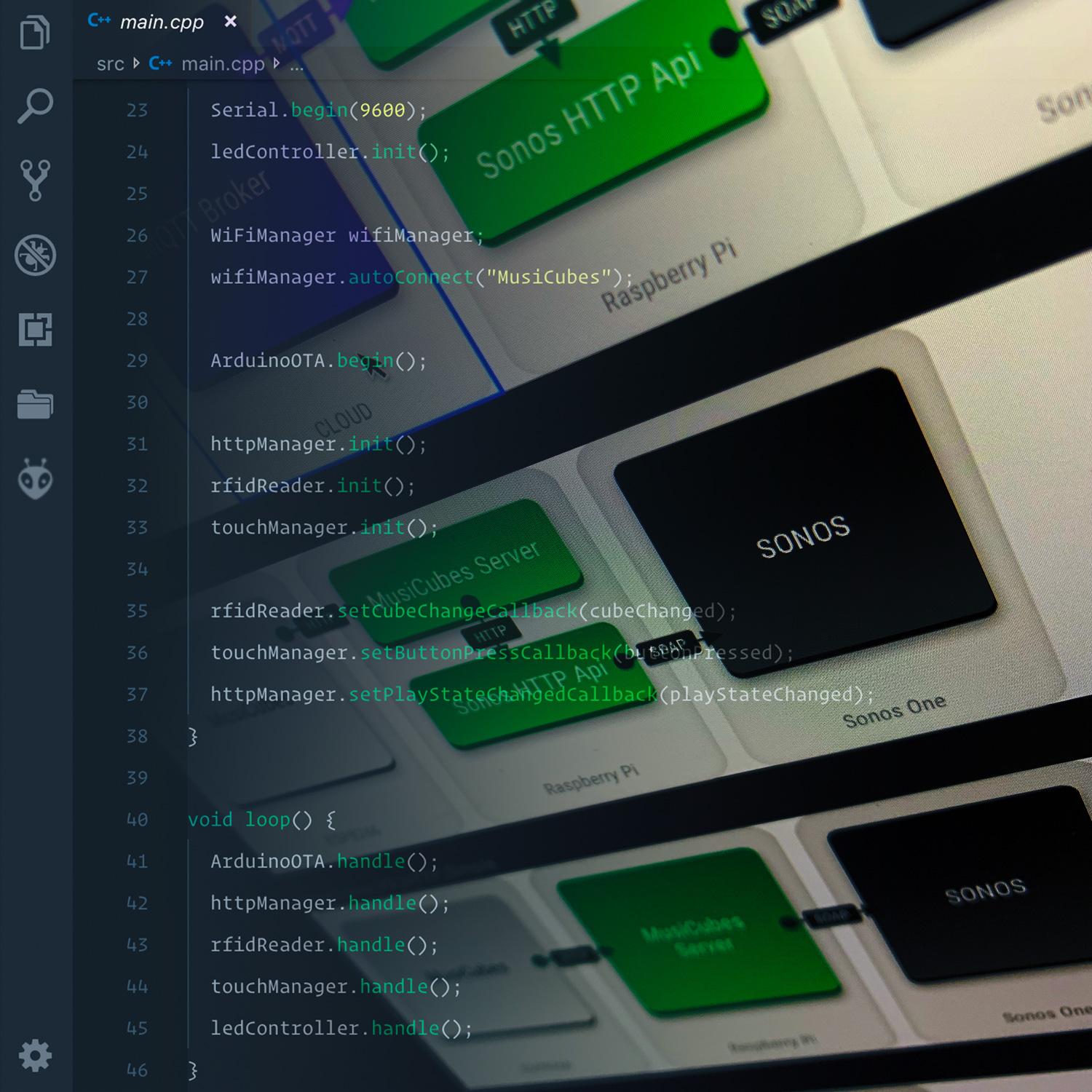
For now, the next step is connecting the ESP8266 to the new central hub of my home sensor system: a MQTT server. Want to know more about this, make sure to stay tuned for part two!

For now, if you have a nice solution for the door sensor, want to point out a stupid mistake, or announce a burglary attempt, please leave a message down below!
HomeSensor: Connecting my house to MQTT.