With the software side of my Home Sensor up and running, there is only one technical issue to solve: the door sensor. A perfect moment to play around with an OP-AMP and Comparator.
HomeSensor: Connecting my house to MQTT.
While most of the sensors of my alarm are open/close sensors, the door sensor has some specific characteristics: when the door is closed, the sensor has a 5K resistance. When the door is opened, it has a 10K resistance. This is due to the anti tamper feature of my alarm. Unfortunately, the sensor is hidden in my door frame, so there isn’t an easy way to change this behaviour.
To solve this, there are two solutions:
- Connect the door sensor to the analog port of my ESP8266 and measure the resistance.
- Use and OP-AMP or Comparator to convert the analog value to a digital signal.
Of course, the first solution is the simplest, and thus I choose the second route!

A perfect moment to start fiddling with an OP-AMP and a Comparator. In this case, the comparator is the best way to solve this issue, and with a little bit of help of my Reddit friends I was able to figure out the difference between these two. The end result of some research and some playing around is the following schematics:

To summarise the working of the above schematics:
- The door sensor, together with R1 creates a voltage divider.
- R2 is an adjustable voltage divider.
- The comparator (A LM393N) compares the voltage of the two voltage dividers on pin 2 (inverting input) and pin 3 (non inverting input).
- If the measured voltage on pin 2 is higher than the measured voltage on pin 3, pin 1 (the output) sinks current (meaning it connects the LED and the ESP8266 pin 7 to ground.)
- Note that R3 isn’t strictly necessary due to the comparators internal resistance. So in my final PCB I left it out.
- This schematic doesn’t include the voltage regulator I use to power the ESP8266. It only focusses on the door issue.
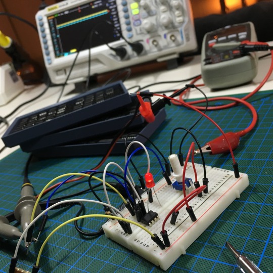
Time for some breadboarding!

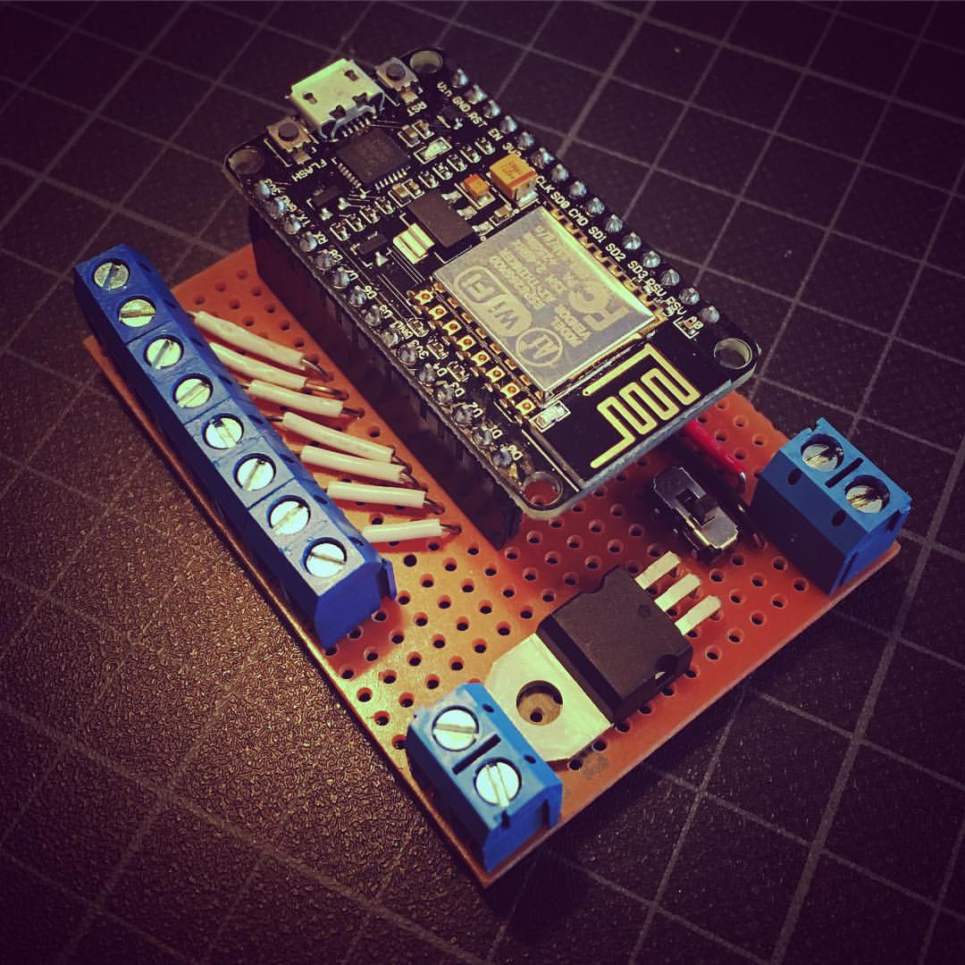
It might look like one big mess of wires, but trust me: it works! I must say the help of my new scope really is helpful. And with everything tested, a delightful night of soldering results in this new perfectly working pcb.

If it fits, it sits! With the ESP8266 on it’s place and the end product works exactly as hoped. Time to mount it in my cup board, connect my sensors and start monitoring my alarm!

The best part of this project? I finally understand the basics of OP-AMP and Comparators! What’s on top of your research list?