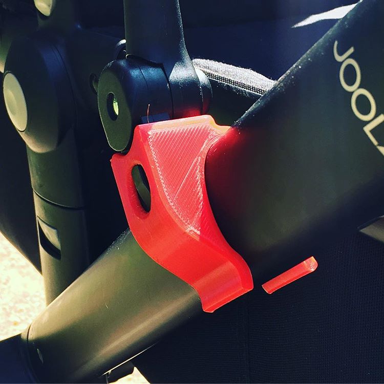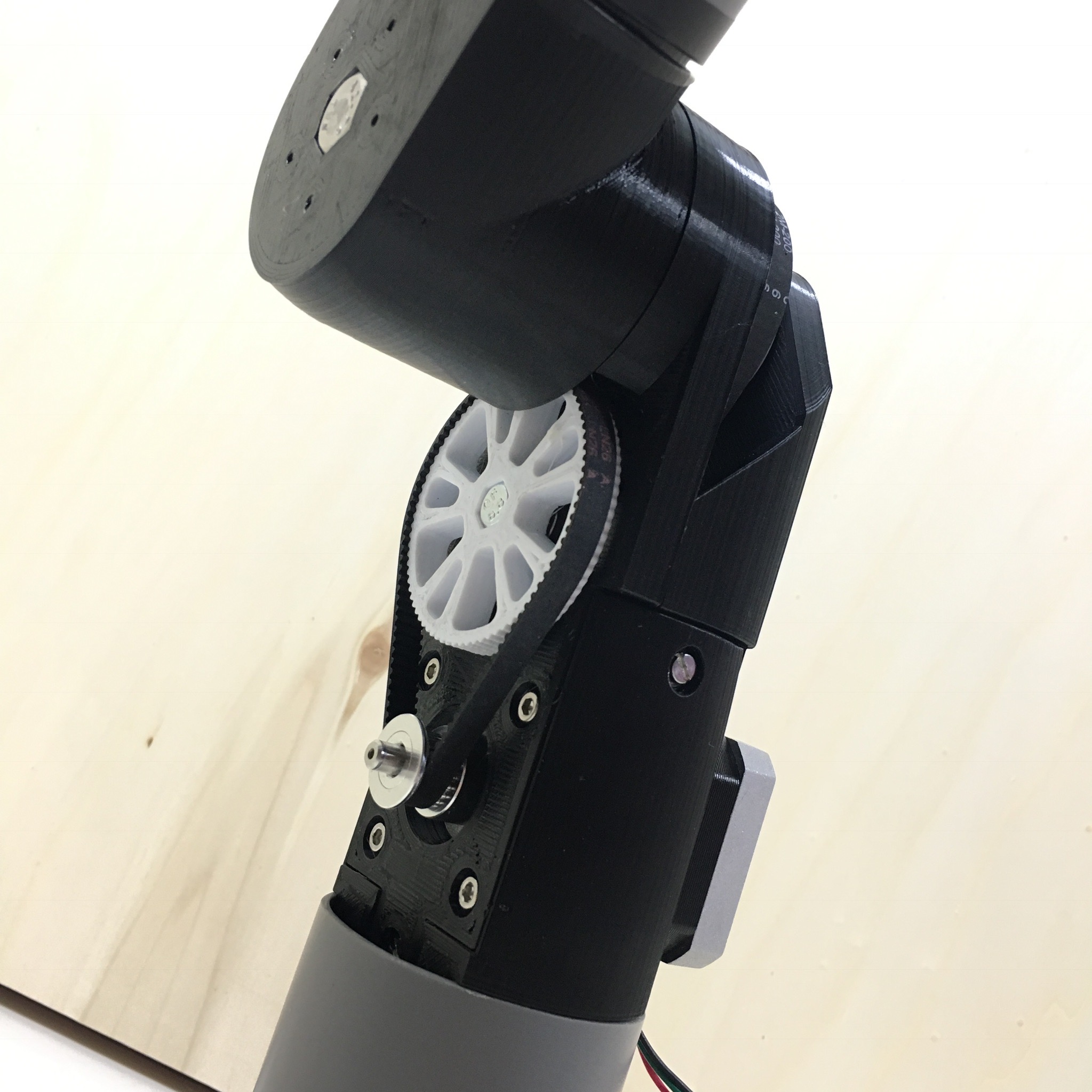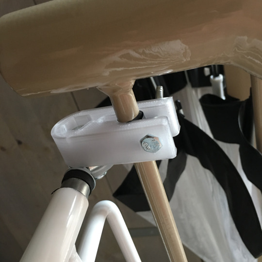
For both my automatic curtains as well as my robot arm joint I ended up using GT2 belts and pulleys. But although printing GT2 pulleys is possible, the 3d printed pulleys tend to skip some teeth quite easily when they are used in high torque applications. Just as an experiment I though to give HTD 5M belts a try.
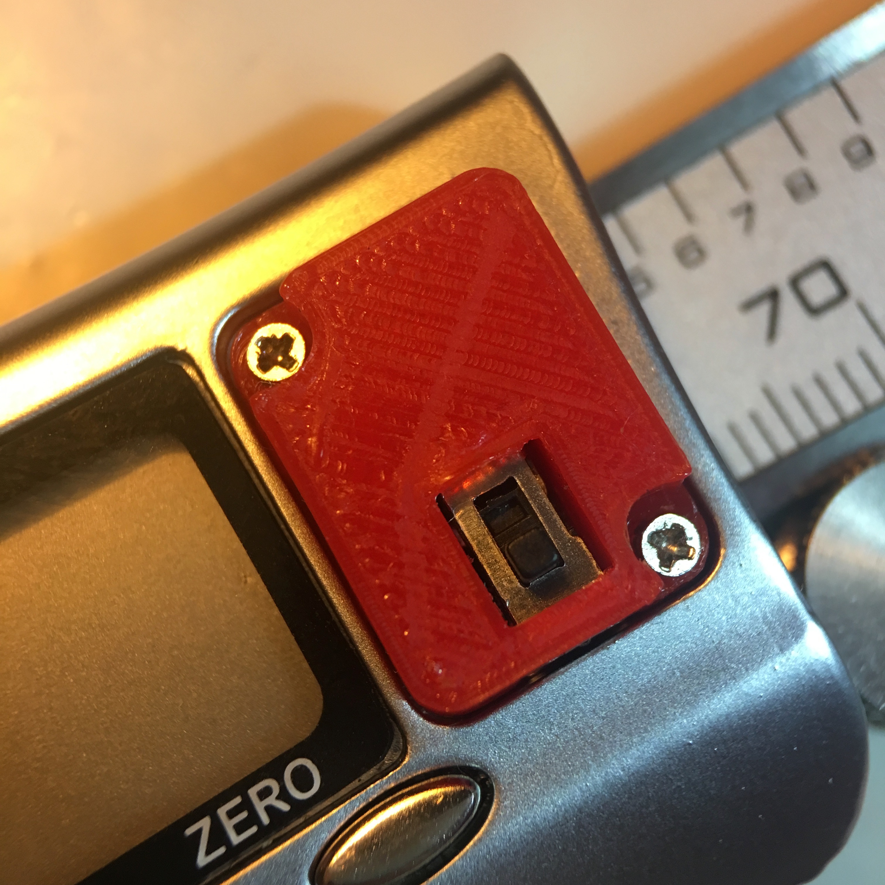
As a starting point I ordered a few belts and pulleys from AliExpress. HTD belts are available with both a 5mm pitch as well as a 3mm pitch. The pitch is the distance from a tooth’s center point to the next tooth’s center point. In this case I used the 5mm pitch version.
After I received the belt and pulleys, it was time to fire up Fusion 360. To make my custom designed pulleys reusable, I’ll make the design parametric, allowing me to change the number of teeth by altering the defined variables.
So the first step is to set all the necessary parameters (‘Modify’ menu > Change Parmeters).

I defined a bunch of variables of which some where calculated on the fly, and some where based on information I found online about the HTD 5M profile. These were the important parameters I defined:
Tolerance: 0.1mmTeethCount: 15Pitch: 5mmPitchCircleDiameter:TeethCount*Pitch/PIToothPitchDistance: 0.5715mm +ToleranceOuterPulleyDiameter:PitchCircleDiameter- (2 *ToothPitchDistance)ToothRadius: 1.545330mm +ToleranceToothDepth: 2.18354mm +ToleranceToothFilletRadius: 0.45380mm +ToleranceWidth: 16mmBore: 8mm
Adding the Tolerance isn’t strictly necessary, but since 3D printers can’t print the perfect dimensions, it really helps in tweaking your design.
Next, we start the design by creating the body of the pulley. This is done by creating a sketch with uses the OuterPulleyDiameter and the Bore parameters. After creating this sketch it is extruded using the Width parameter.
Next, we drag the tooth sketch on the body’s top surface. It starts with a circle which has a diameter of ToothRadius * 2, and setting ToothDepth as the distance between the bottom of the circle and the border of the body. Two vertical lines between the circle and the border of the body will help to create a nice cutout.
After finishing the the sketch, we make the cutout bij selecting the correct faces and using an 'all trough’ cut.
Next we add fillets to the body by selecting two edges and using the ToothFilletRadius as the radius.
Last but not least, we create a circular pattern (Create > Pattern > Circulair Pattern). The pattern type is 'Features’ and uses the last two features (Extrude & Fillet) as the object to repeat. The pattern is based on the Y-axis and the quantity is set to the TeethCount parameter.
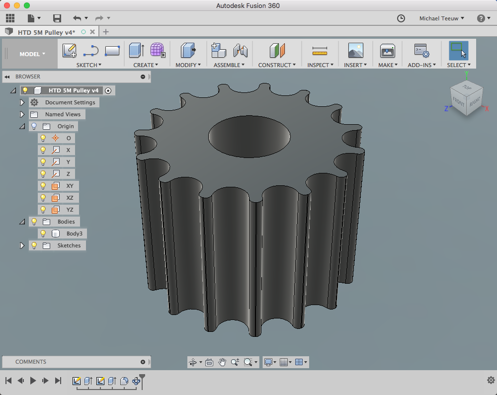
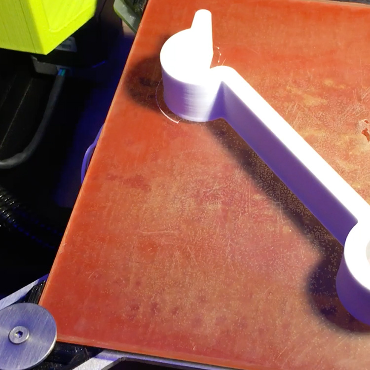
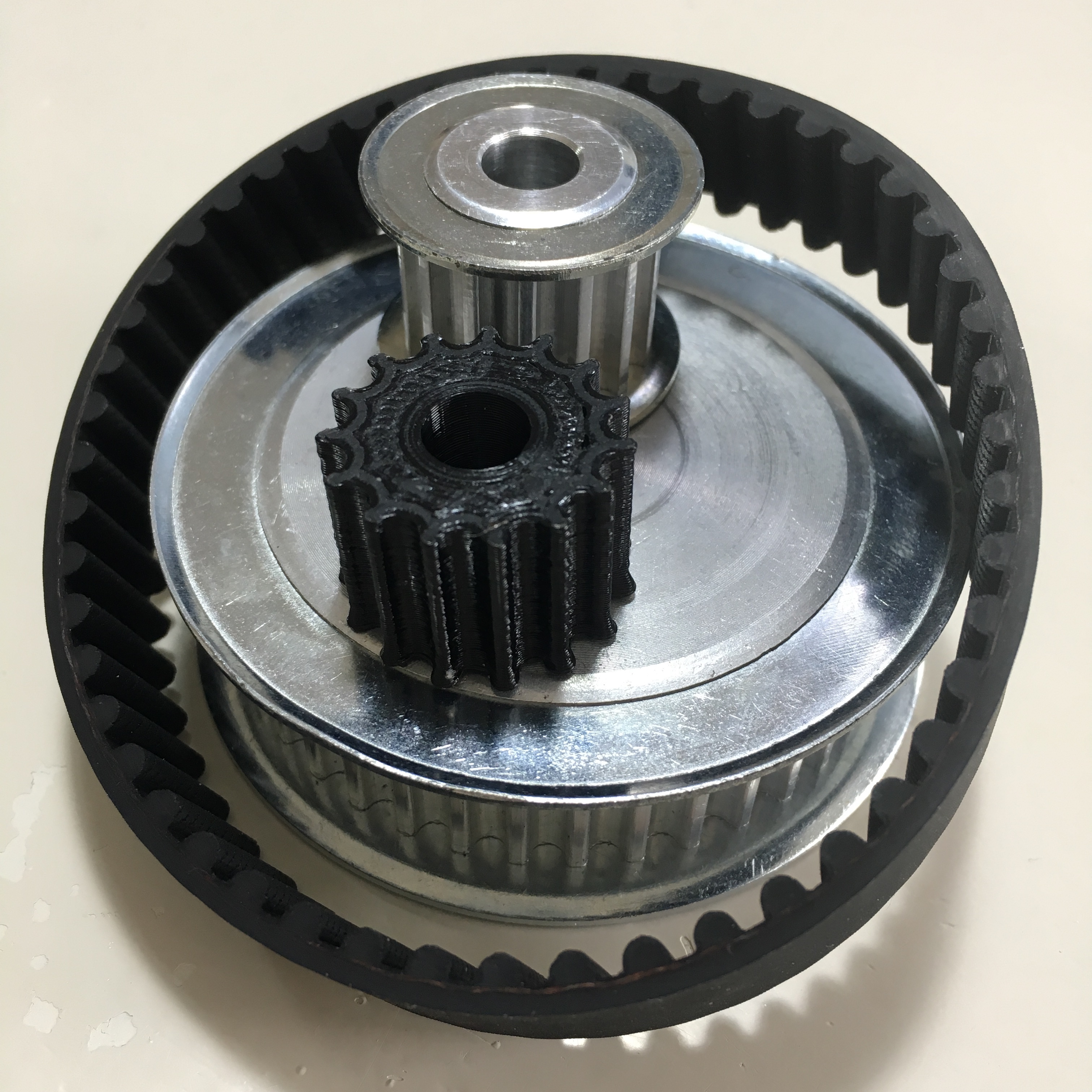
This results in a perfectly drawn HTD 5M pulley. Of course, the design can be improved by adding flanges and by adding set screws. For now, let’s just fire up the 3D printer!
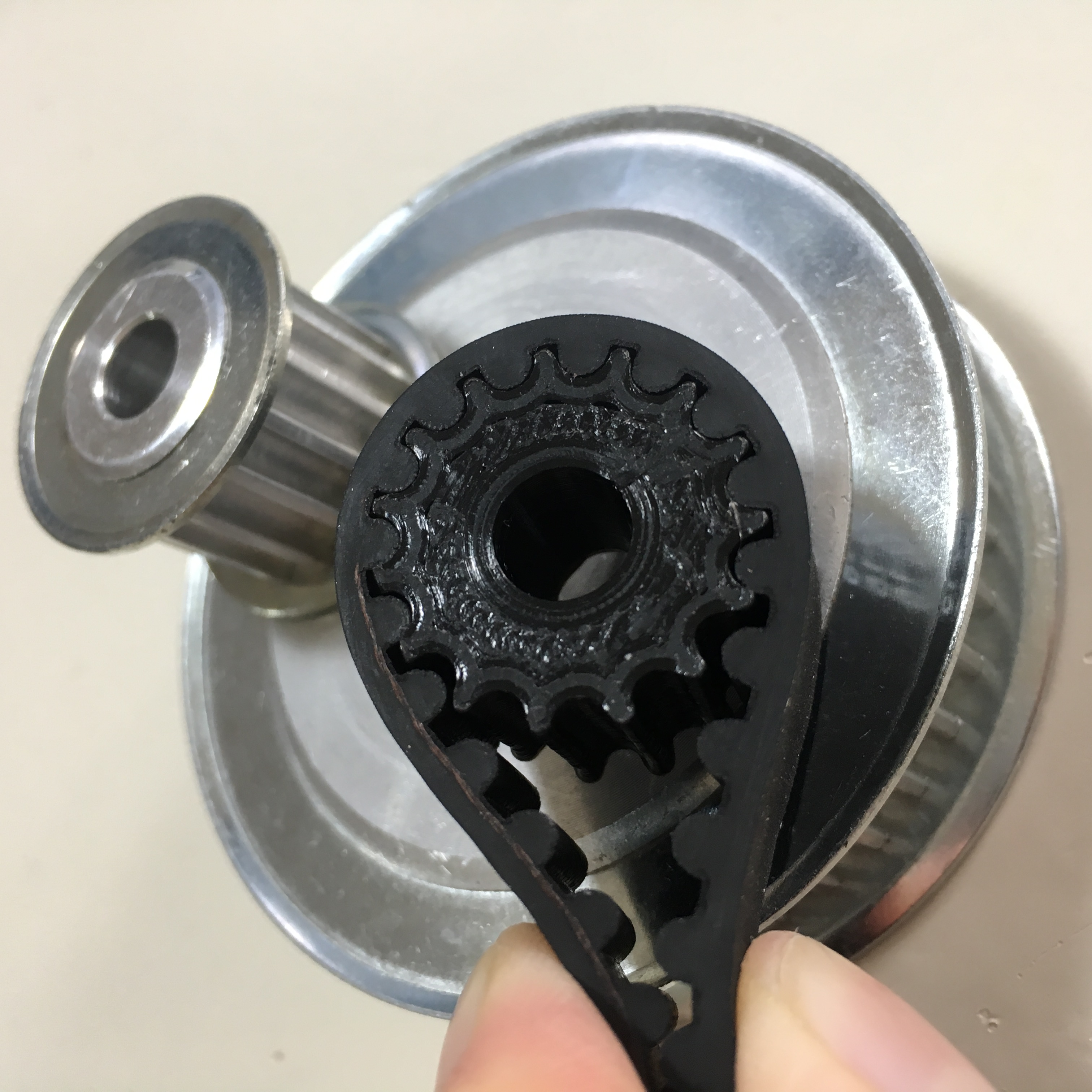
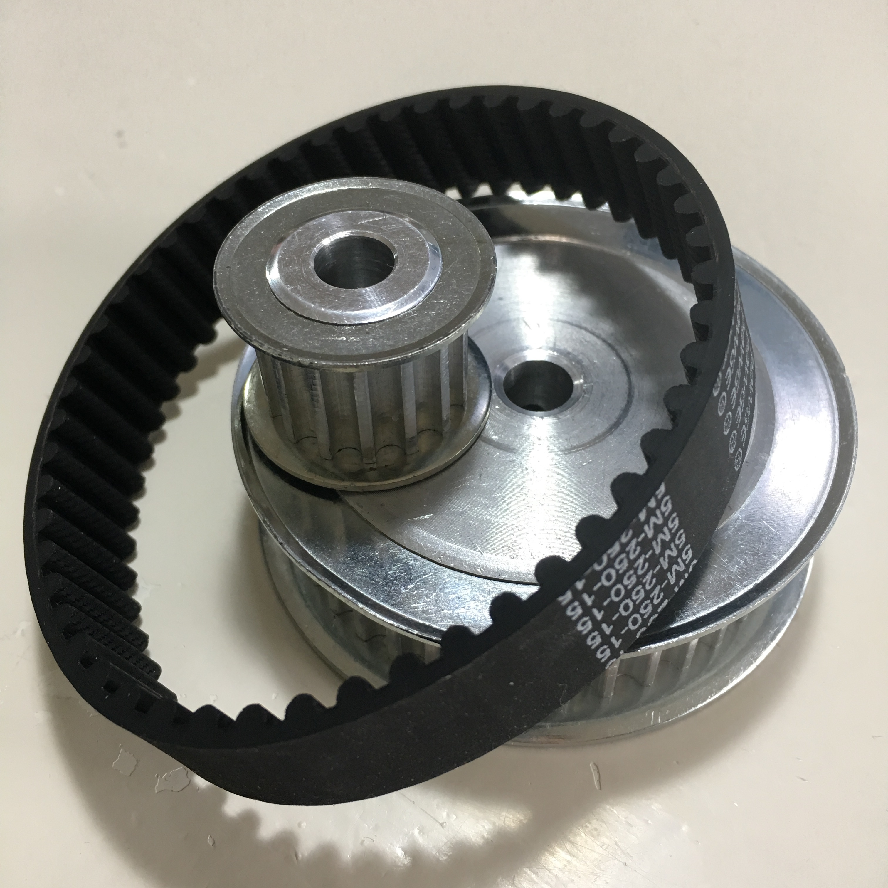
As you can see, the pulley fits perfectly in the belt. And with the bigger teeth (compared to the GT2 pulley), belt skipping is less likely to happen.
The parametric design allows us to generate any size of pulley. Check out the 30 teeth version below:

Want to checkout or reuse my design, download the Fusion 360 sketch here: https://a360.co/2GwtH9o
Do you have any ways to improve this parametric design? Leave a comment down below.