After building the Enclosure for my Lulzbot Mini 3D Printer, I started to worry my Printer wouldn’t like the built up heat. Although higher temperatures are usually an improvement for the print quality, it might affect the hardware. To prevent this, I decided to add a temperature regulated cooling fan.
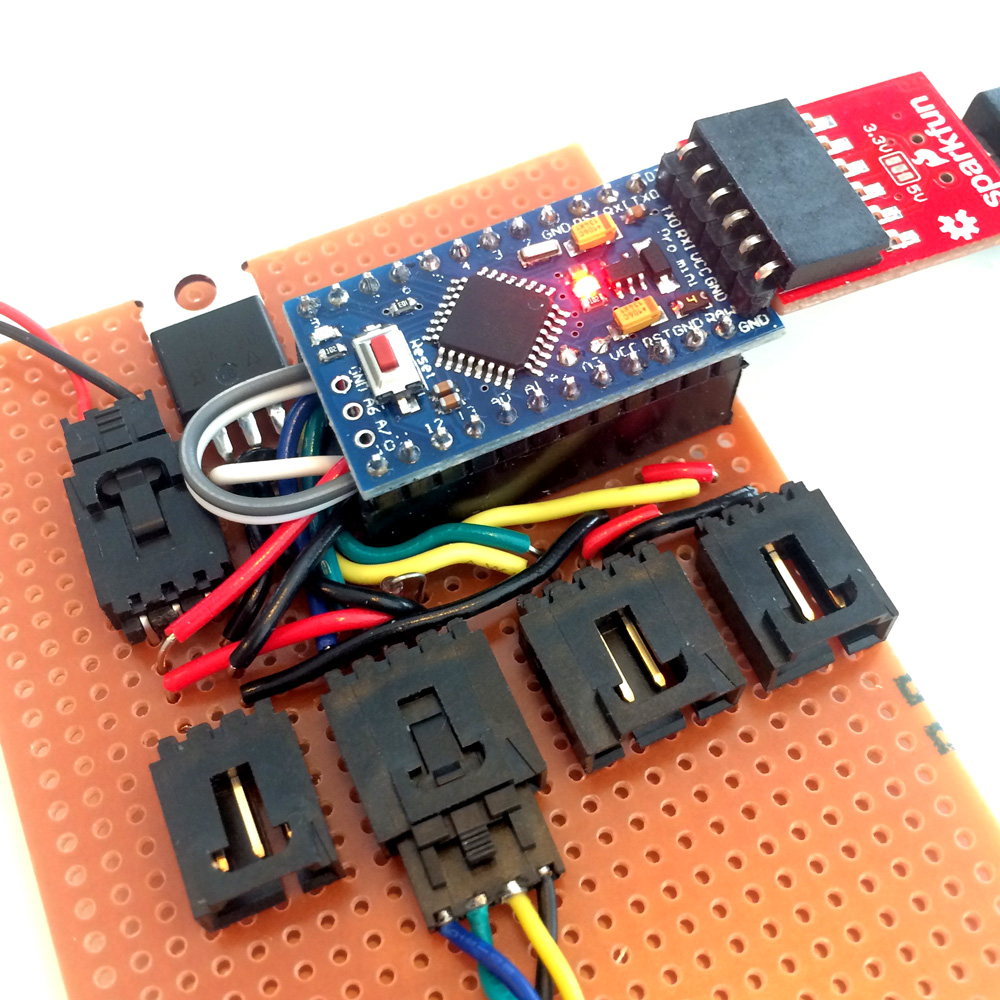
With the help of an Arduino Pro Mini, I started playing around with the a four wire fan. The benefit of a 4 wire fan is that has a sense wire to measure the RPM and a control wire to control the speed of the fan using Pulse Width Modulation (PMW).
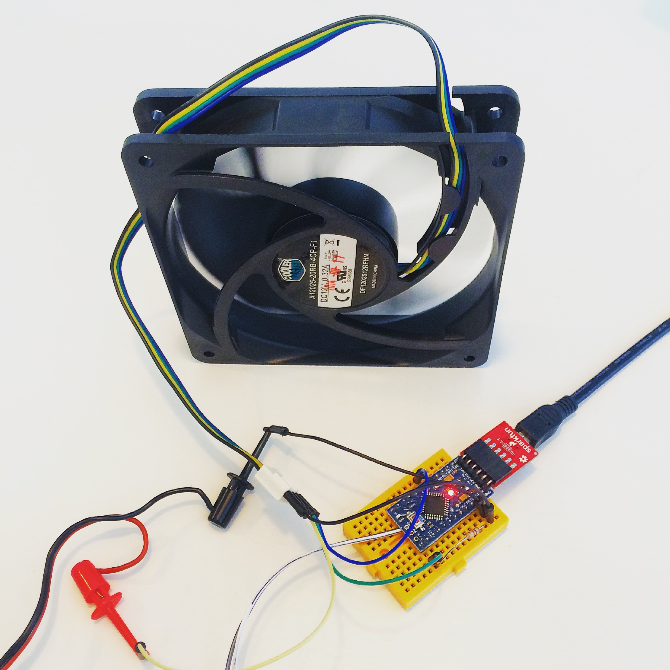
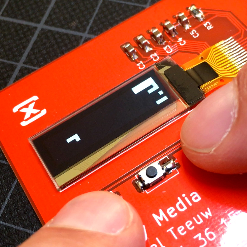
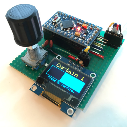
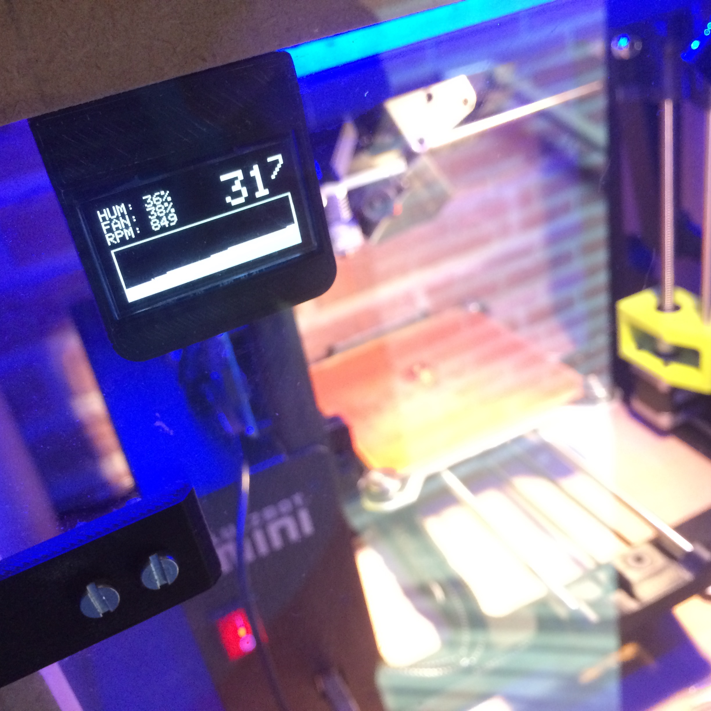
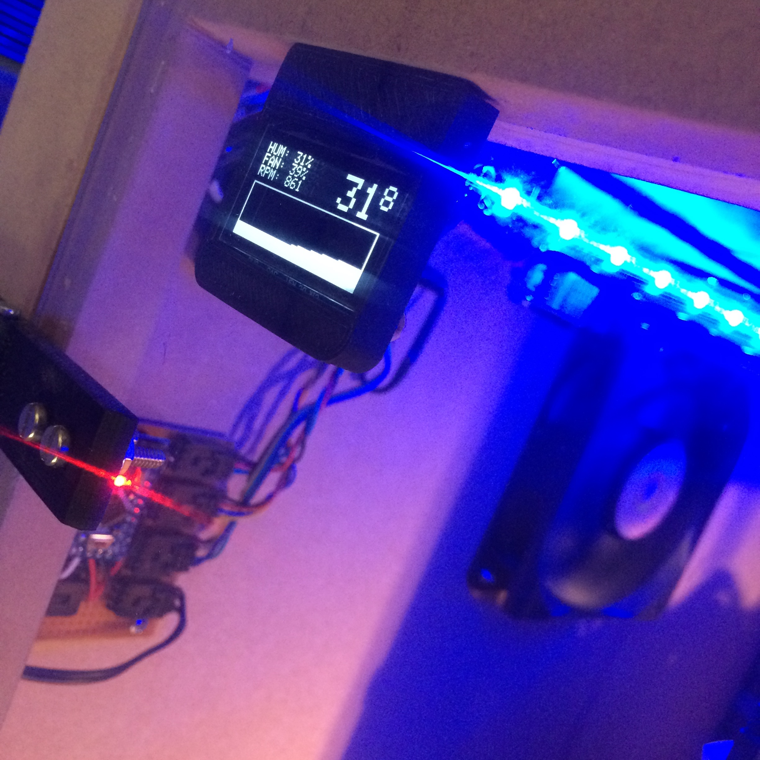
Adding a OLED screen allowed me to print out the RPM and see the results of random generated temperatures. It also gave me the opportunity to play around with a possible layout. On the breadboard, I used a small 2 color OLED screen, but the final version will be built upon a 1.3" white OLED.
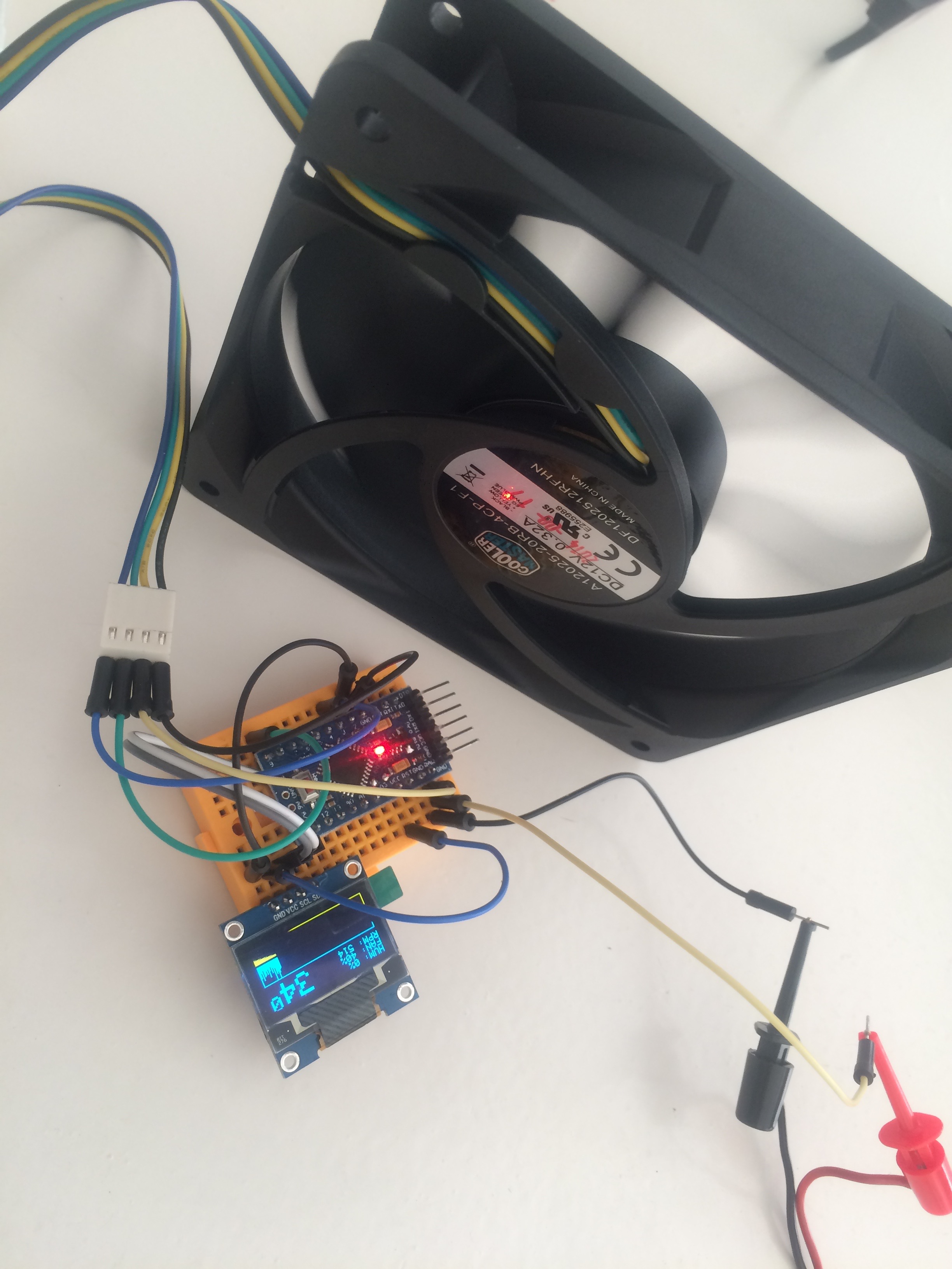
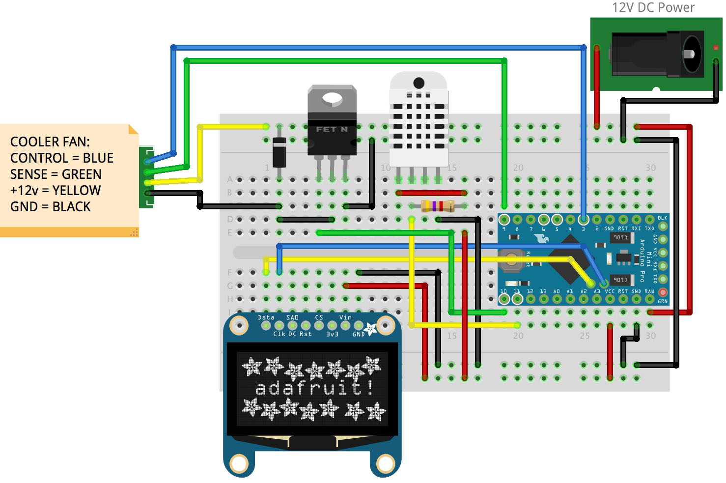
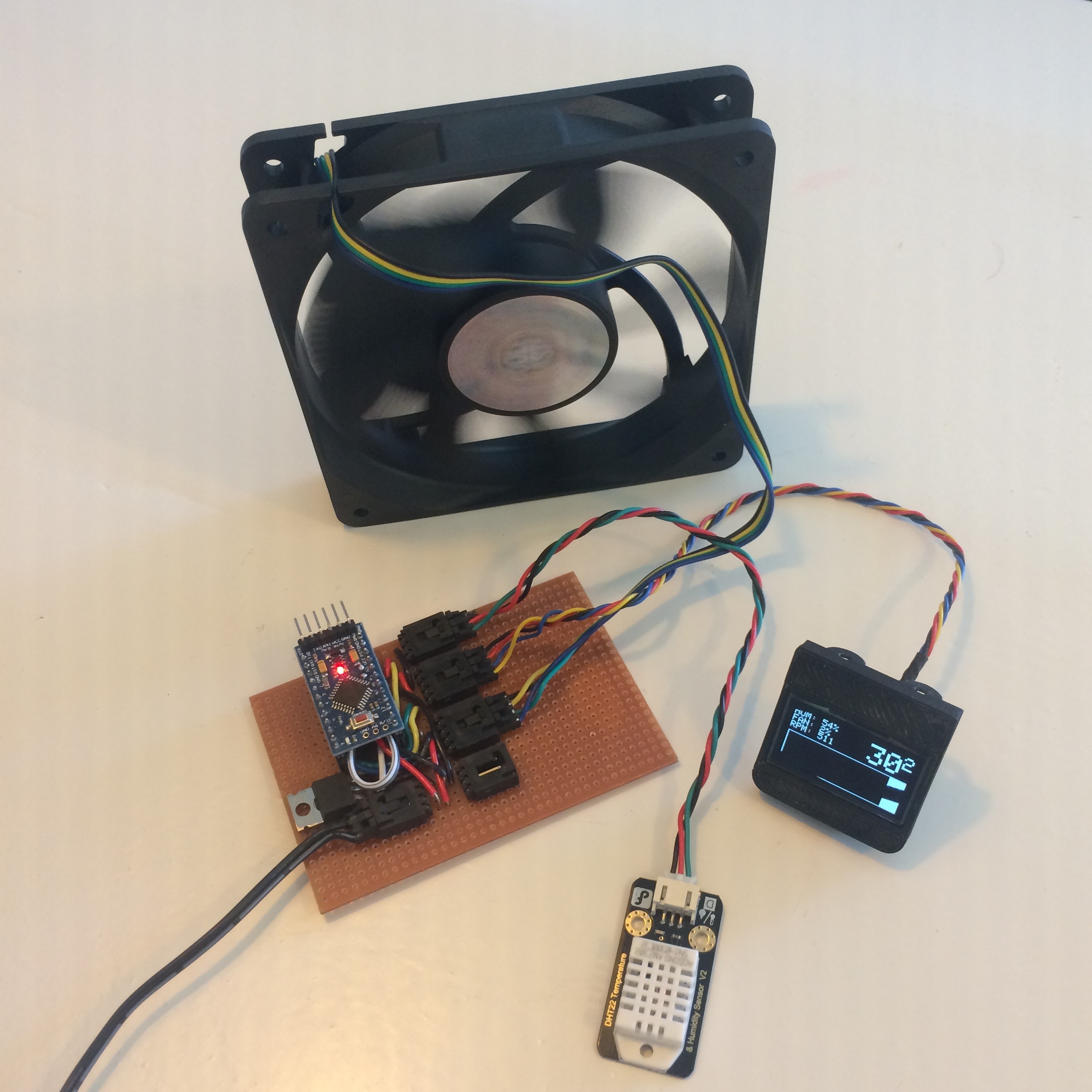
After adding a DHT22 humidity and temperature sensor, most of the necessary parts were included. One issues though: the fan only allows speed control. Is isn’t possible to completely turn of the fan using PMW. To solve this, I use an Arduino controlled MOSFET to disconnect the power to the fan. The final schematics look like this:
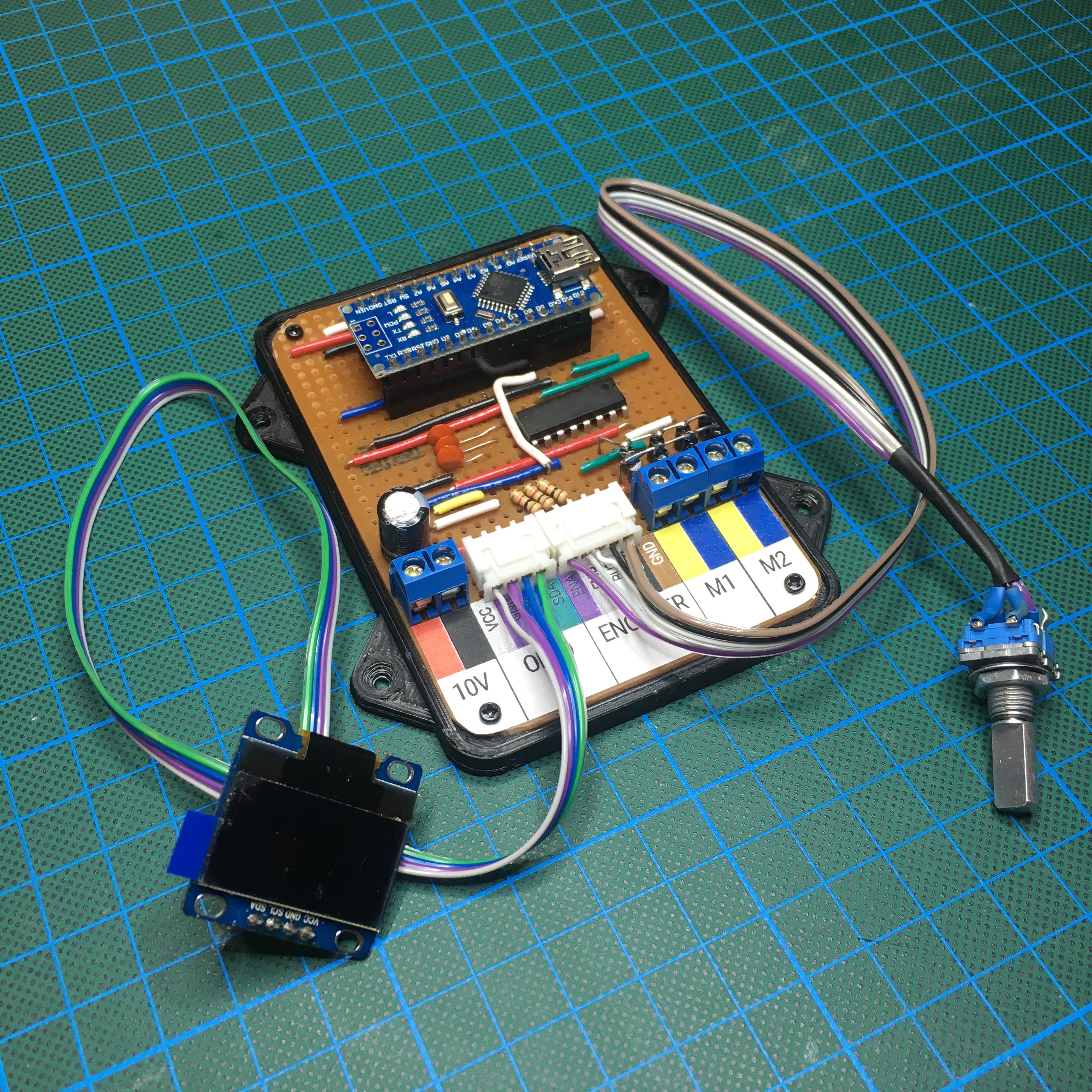
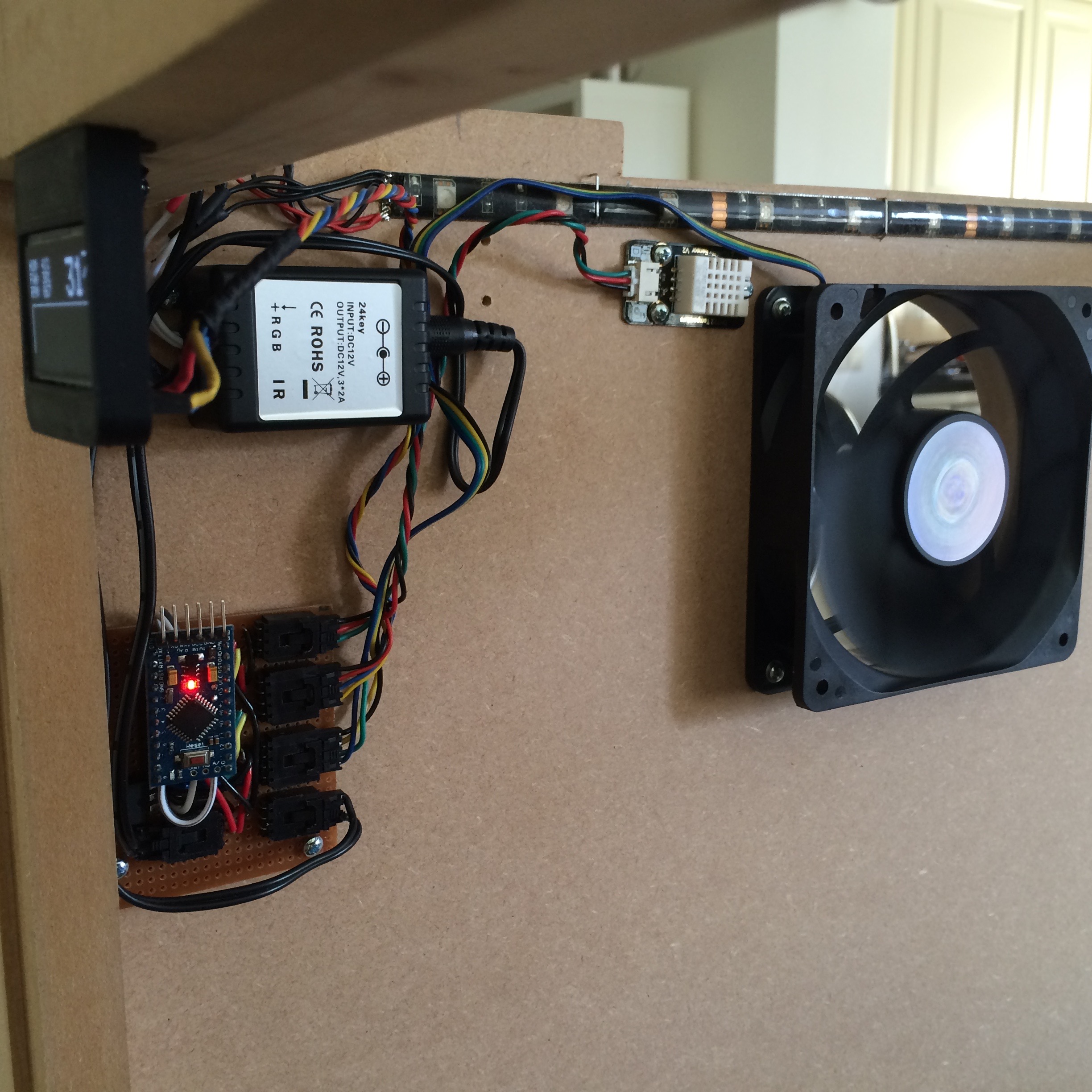
With everything figured out, and thoroughly tested, it is time to create a more permanent solution. Using some perfboard and a lot of jumper wires, I managed to create the final control board.
After checking all the connections, and soldering all the connectors, the full package is completed. With extremely hot summer days and a soldering iron on my desk, the working fan is a welcome addition to my workplace.
With everything up and running, it was time to tweak the software. For instance, I discovered that the first 25% of the PMW signal doesn’t affect the fan speed. As you can see in the following picture, the fan will run around ~500 RPM, even when the fan speed is set to 1%. So the effective PMW signal must be between 64 and 255. Luckily, this was an easy fix.
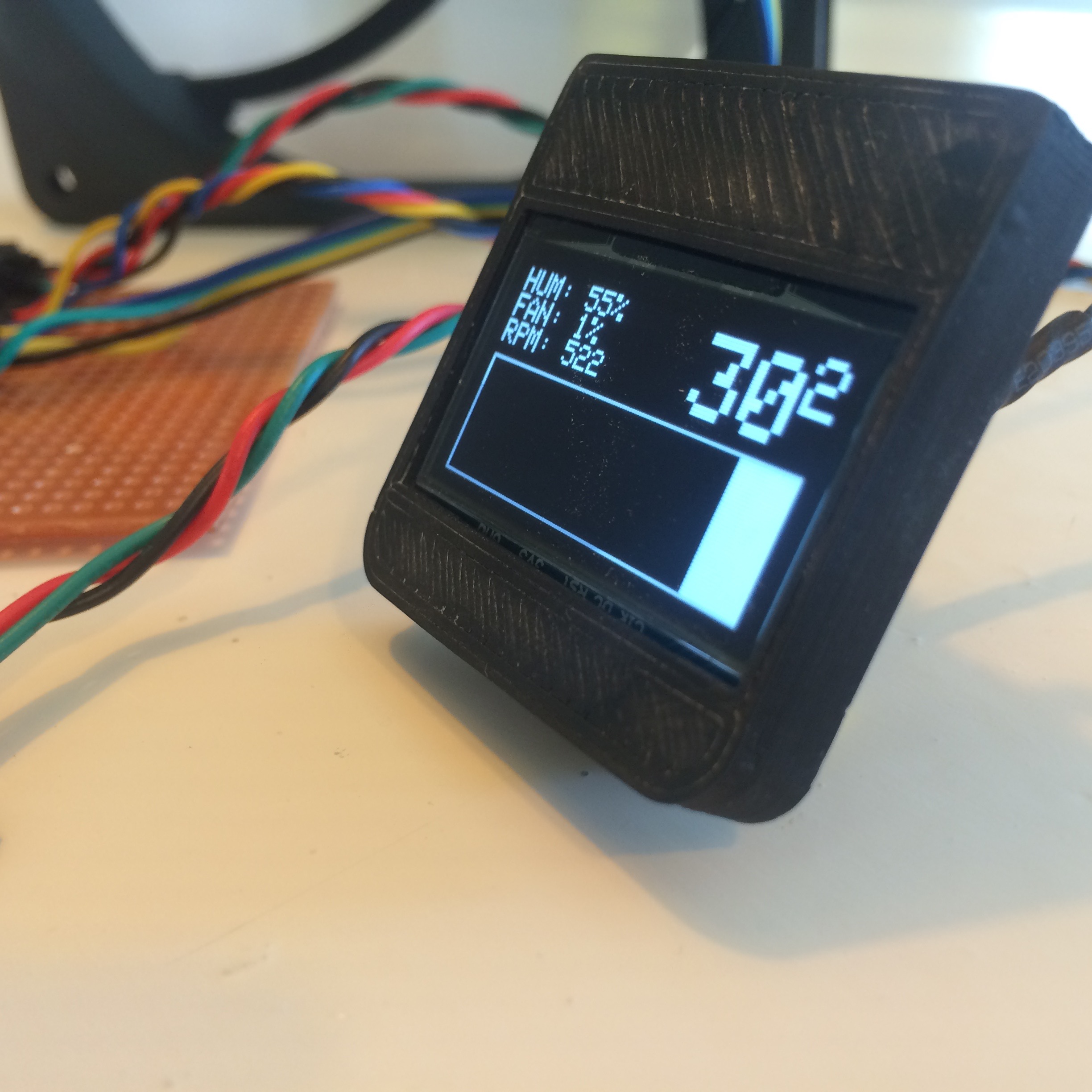
Additionally it gave me the possibility to figure out what to do with the graph. Initially I used it to display the history of the temperature. But since you’ll never know the maximum temperature, this didn’t gave a clear indication. Eventually I choose to display the fan speed history.
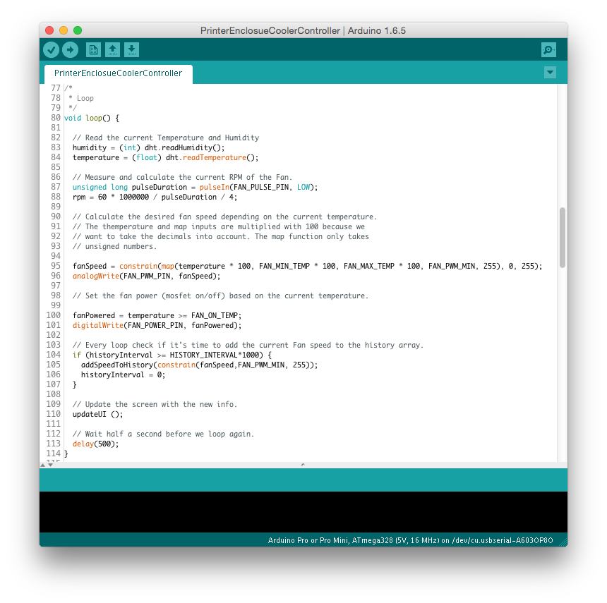
The main goal of the software is of course the speed control of the fan. Eventually I choose to control it as follows:
- Below 25 degrees the fan is turned off.
- Between 25 and 30 degrees the fan will run on the lowest speed. (25%)
- Between 30 and 40 degrees the fan will be controlled between 25% and 100% of it’s power.
- Above 40 degrees, the fan will run full speed.
If you’re interested in the code, check out the GitHub repository.
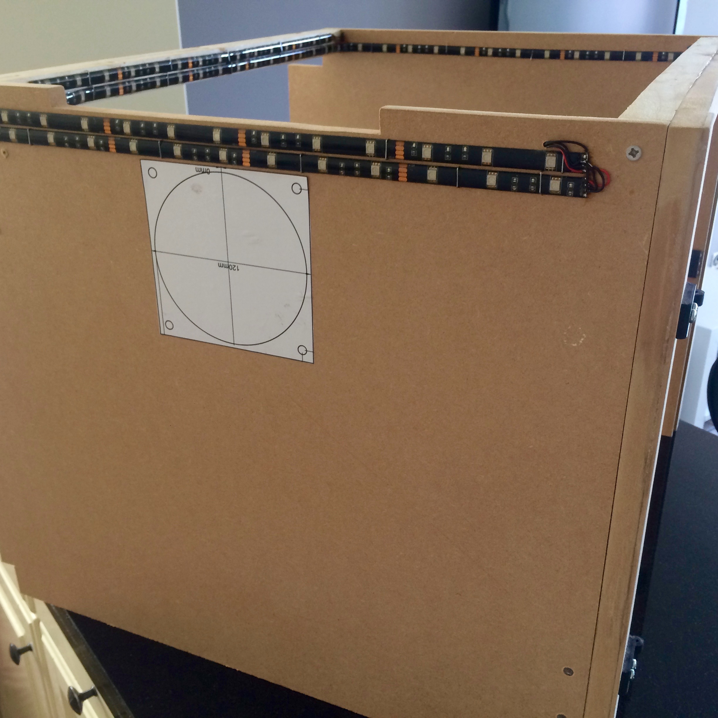
With the electronics and software finished, it is time to jump to the next task: put everything in place. With a printed template, I choose the perfect spot to saw a hole using a jig saw.
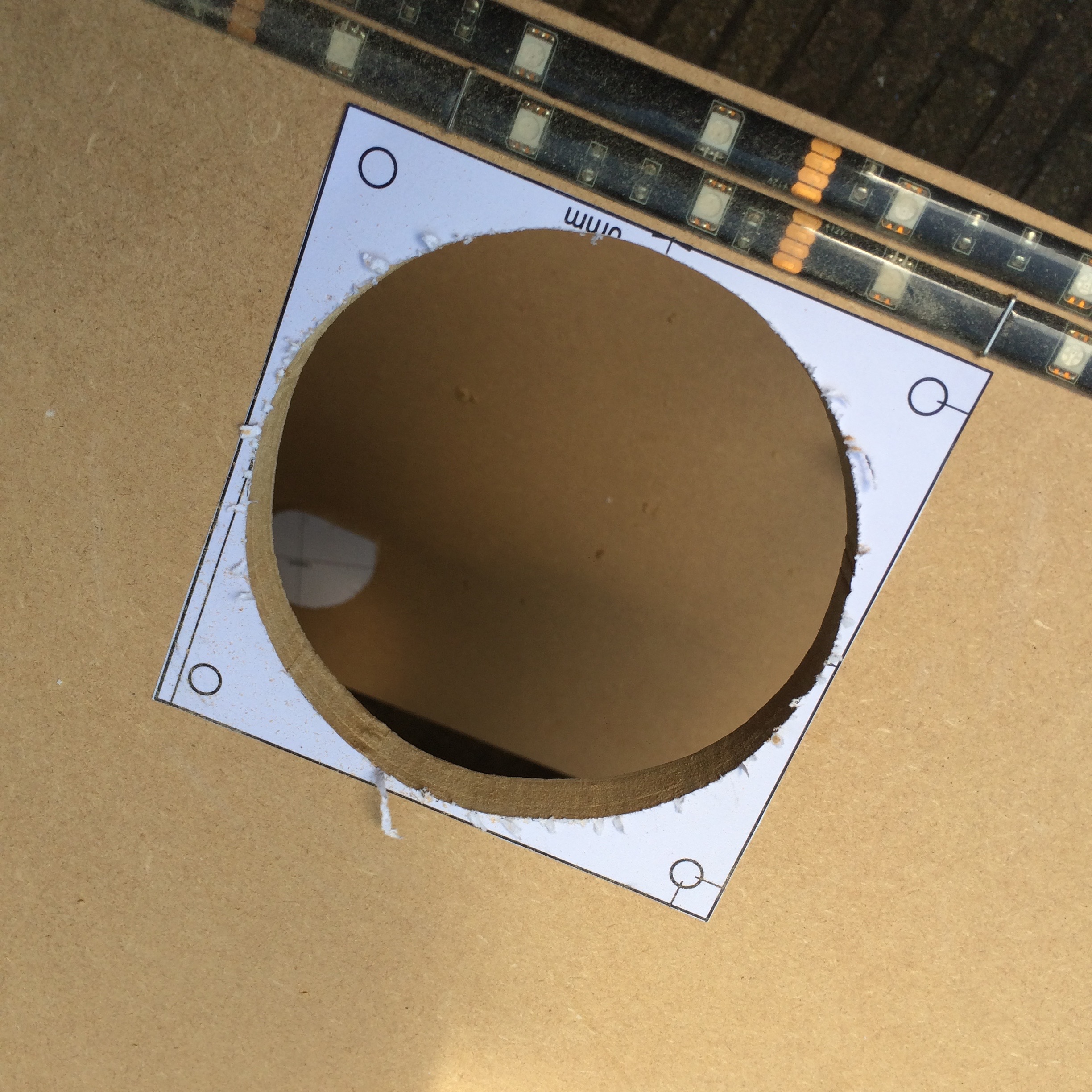
With a lot of patience and my tongue between my teeth, I managed to saw a hole without damaging anything else. Miracles do happen!
I mounted everything in place and a small testdrive followed. The fan started spinning, the display showed the desired information and the sensor picked up the temperature and humidity. Once again, a small miracle!
The end result is better then I initially hoped. Not only does it look cool (see what I did there?), but it really seems to keep the temperature between 30 and 40 degrees centigrade.
With summer days like this week, I couldn’t have timed this addition to my enclosure any better. Time for some hot summer printing!
Of course there is always room for improvement, so let me know what you think in the comments down below!