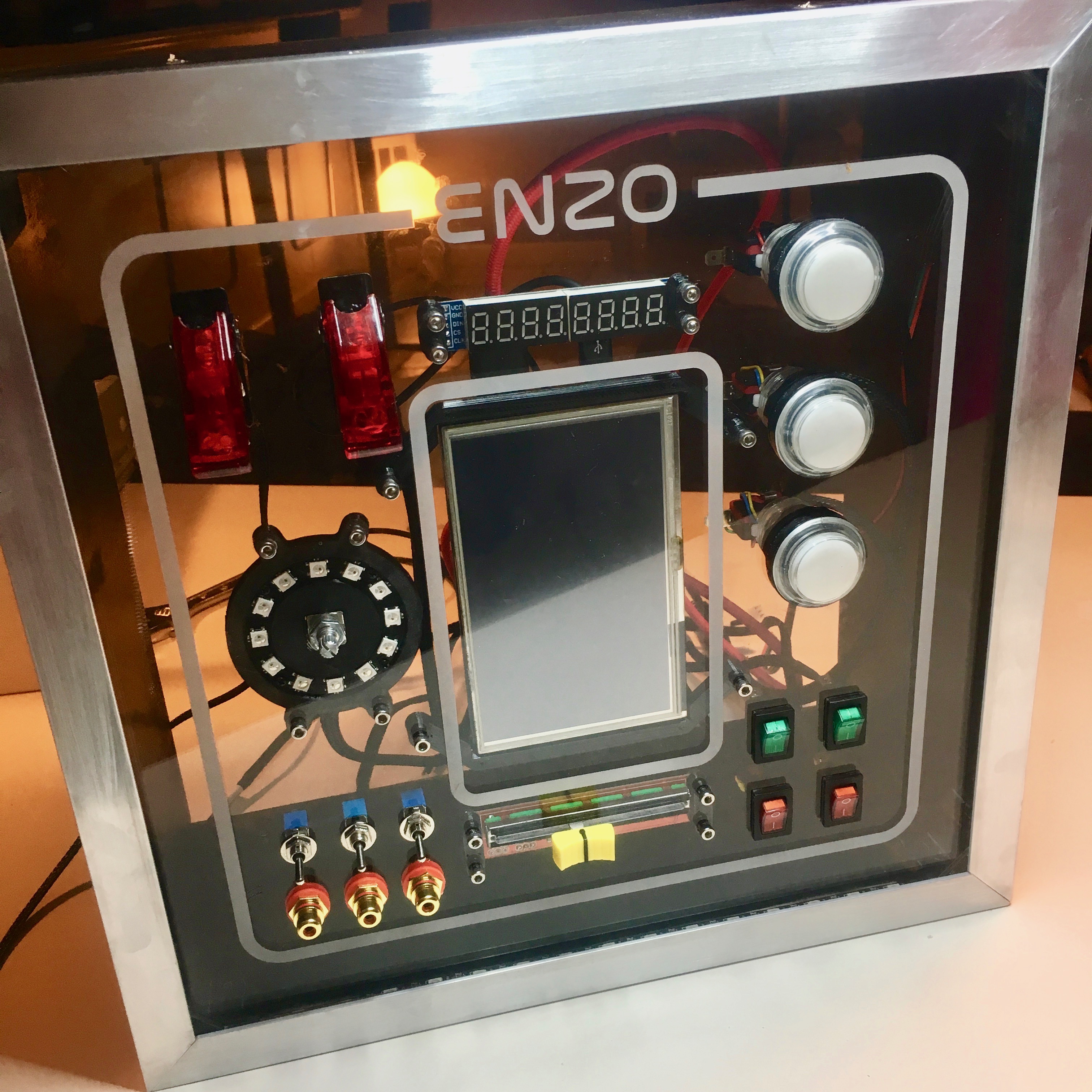
Now that the activity board casing is done. It’s time to start the wiring of all the components. A tedious job which I take way too serious.
Activity Board: Spray Away!
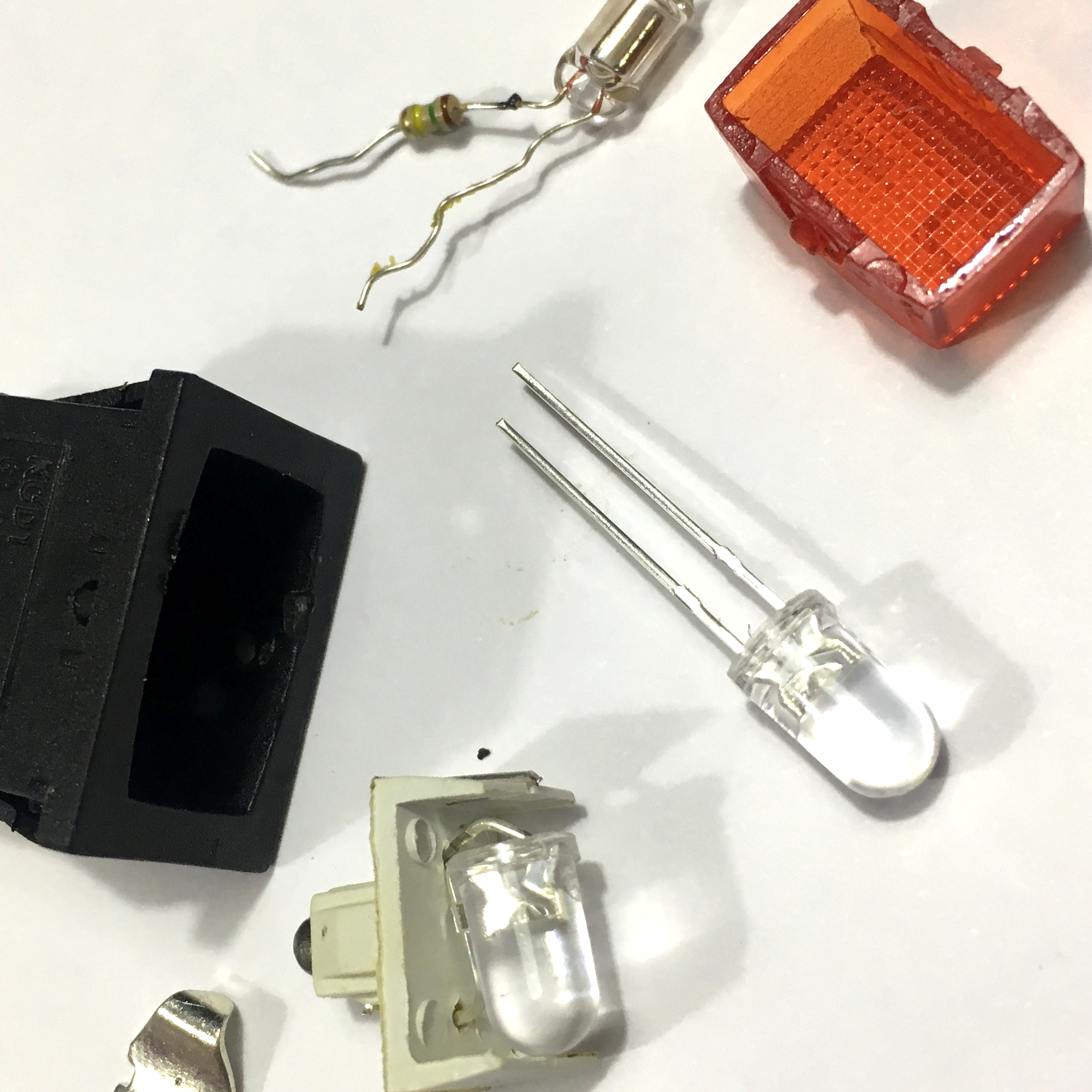
This week: the 3 colorful arcade buttons. As I have shown before on my Instagram, I’ll be replacing the default white leds with WS2812 RGB LED’s (aka Neopixels). To make sure they won’t suffer from any interference, I’ll add a 0.1uF 1206 capacitor across VCC and Ground of the WS2812. A little bit of double sided tape helps me to keep the LED in place while soldering the wires and caps to the LEDs.

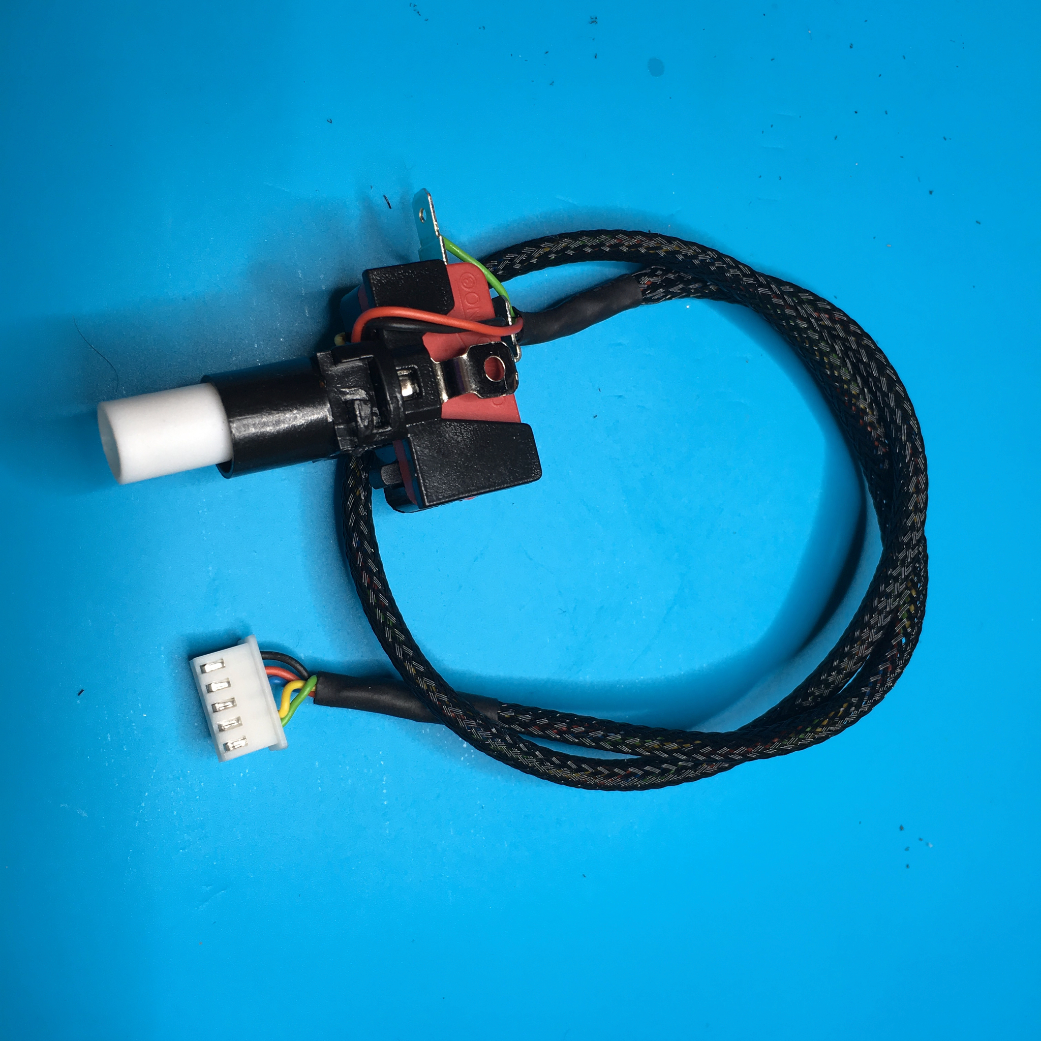
After a night of soldering, I end up with 3 buttons and a bunch of wires. Of course, all these buttons need one extra wire to check the state of the button. Resulting in 5 wires per arcade button:
- Green: The button’s signal wire. (Missing in the picture below)
- Yellow: Data In for the WS2812.
- Blue: Data Out for the WS2812.
- Red: VCC for the WS2812.
- Black: Ground.

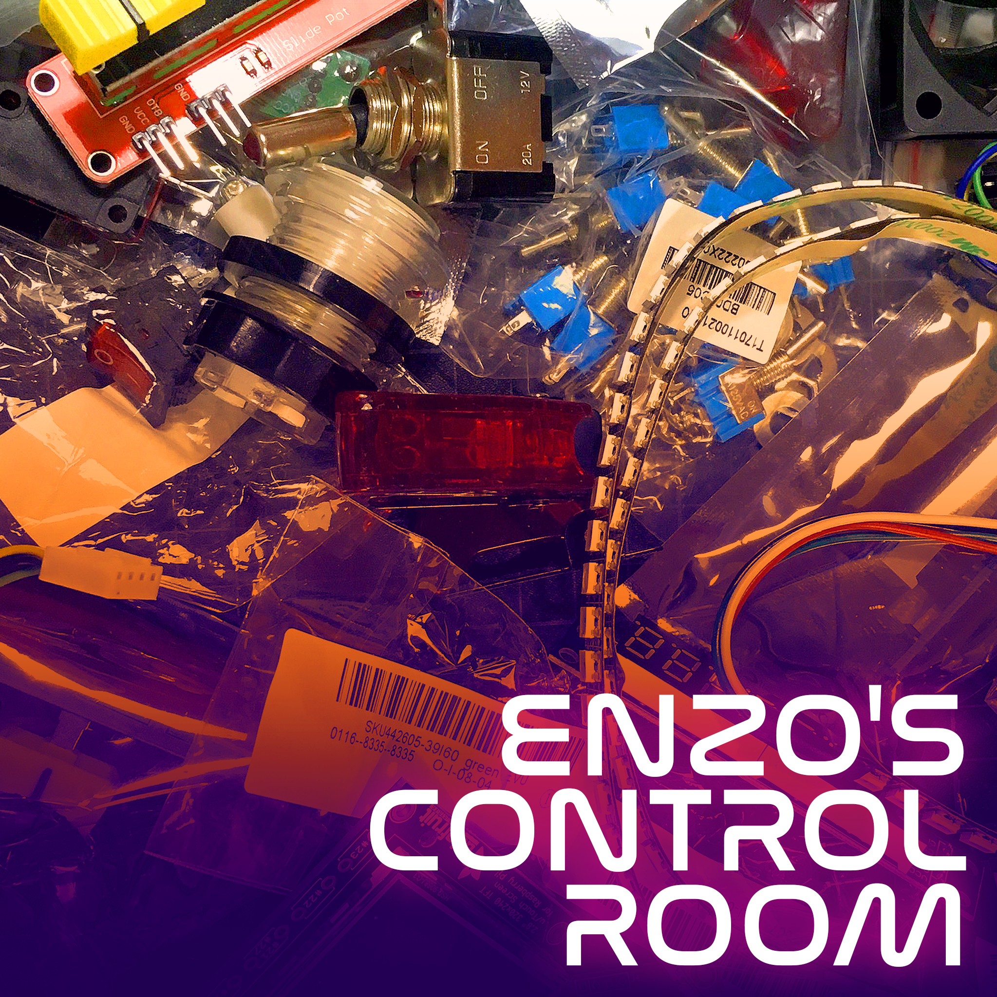
Of course, my boy’s activity board needs some serious professional grade wiring. So to make a tedious job even more cumbersome, I decided to use cable black braided cable sleeves for all the wires. And add JST connectors to all the font panel components. That will keep me busy for a while …
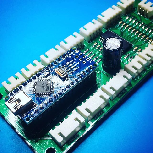
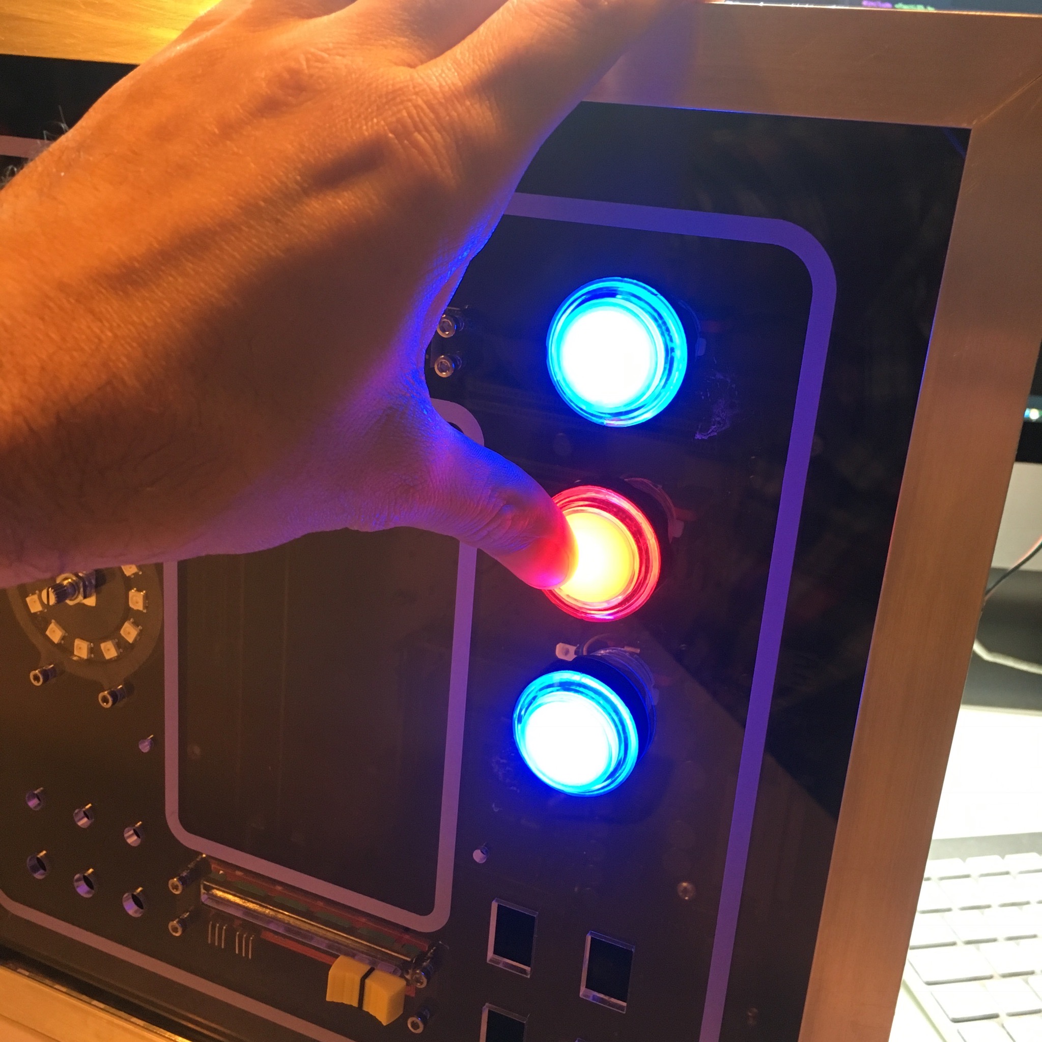
Now to make sure I wired everything correctly, I connected everything onto a breadboard. Wires. Wires everywhere!
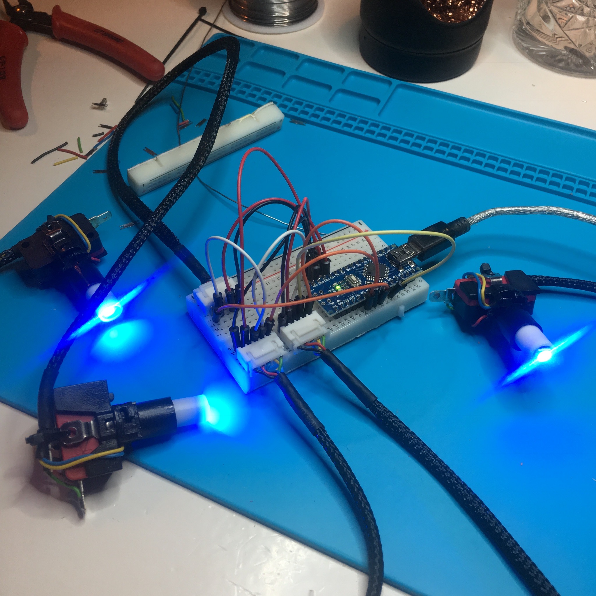
Luckily, it turned out I wired everything correctly and didn’t damage any of the WS2812’s with my beefy soldering iron.
With the wiring and test done, it’s time to make the effect a bit more colorful. Time to start playing with the FastLed library!
Let’s start with including the necessary libraries and defining some constants.
#include <Arduino.h>
#include <FastLED.h>

#define NUM_LEDS 3
#define NUM_BUTTONS 3
#define DATA_PIN 7
Next, let’s create the necessary variables:
byte buttons[3] = {3, 4, 5}; // An array with the button PINS
CRGB leds[NUM_LEDS]; // An array with the LED color states.
CHSV chsv = CHSV( 0, 255, 255); // The next color to be assined.
The LED’s are defined as RGB values. The chsv variable is a color in “Hue, Saturation and Value” color-mode. This will allow me to shift trough all the available hue values.
Time to run the setup. Which does nothing more then setting up the pin states and the initial LED colors.
void setup() {
    FastLED.addLeds<NEOPIXEL, DATA_PIN>(leds, NUM_LEDS);

    for (byte button = 0; button < NUM_BUTTONS; button++) {
      pinMode(buttons[button], INPUT_PULLUP);
    }

    for (int led = 0; led < NUM_LEDS; led++) {
      leds[led] = CRGB::Red;
    }
}
And, last but not least, the main run loop.
void loop() {
  for (byte button = 0; button < NUM_BUTTONS; button++) {
    if (!digitalRead(buttons[button])) {
      chsv.hue++;
      leds[button] = chsv;
    } else {
      leds[button].fadeToBlackBy(1);
    }
  }
  FastLED.show();
  delay(5);
}
This loop iterates trough all the buttons, checking the current button states. If a button is pressed, the hue of the chsv variable is increased and assigned to the corresponding LED. If the button isn’t pressed, the corresponding LED is slowly faded to black.
After all buttons are checked, the WS2812’s are updated with the FastLED.show() command, and the loop waits for 5 milliseconds.
As simple script, which results in the following effect.
Of course, this isn’t the final effect I got in mind for these buttons. But for now, it will keep my boy my wife me busy!
Activity Board: Assembling the panel