Now that the prototype is finally complete, it is time to start assembling the 4 final motor units: a combination of wood working, 3D printing and some minor cussing. Because I expect some small adjustments along the way, I’ll make the units piece by piece.
Automatic Curtains: Prototyping complete!
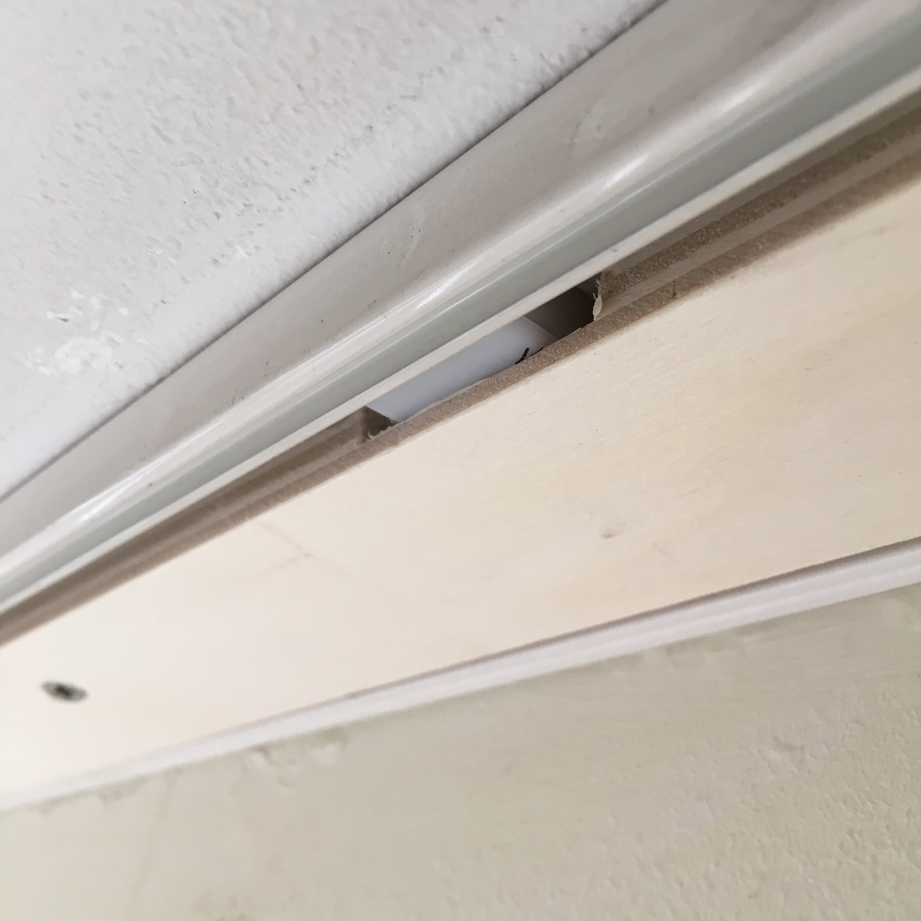
Because my curtain rails are currently mounted to the ceiling using plastic mounting blocks, I can’t just screw the motor units straight onto the ceiling.
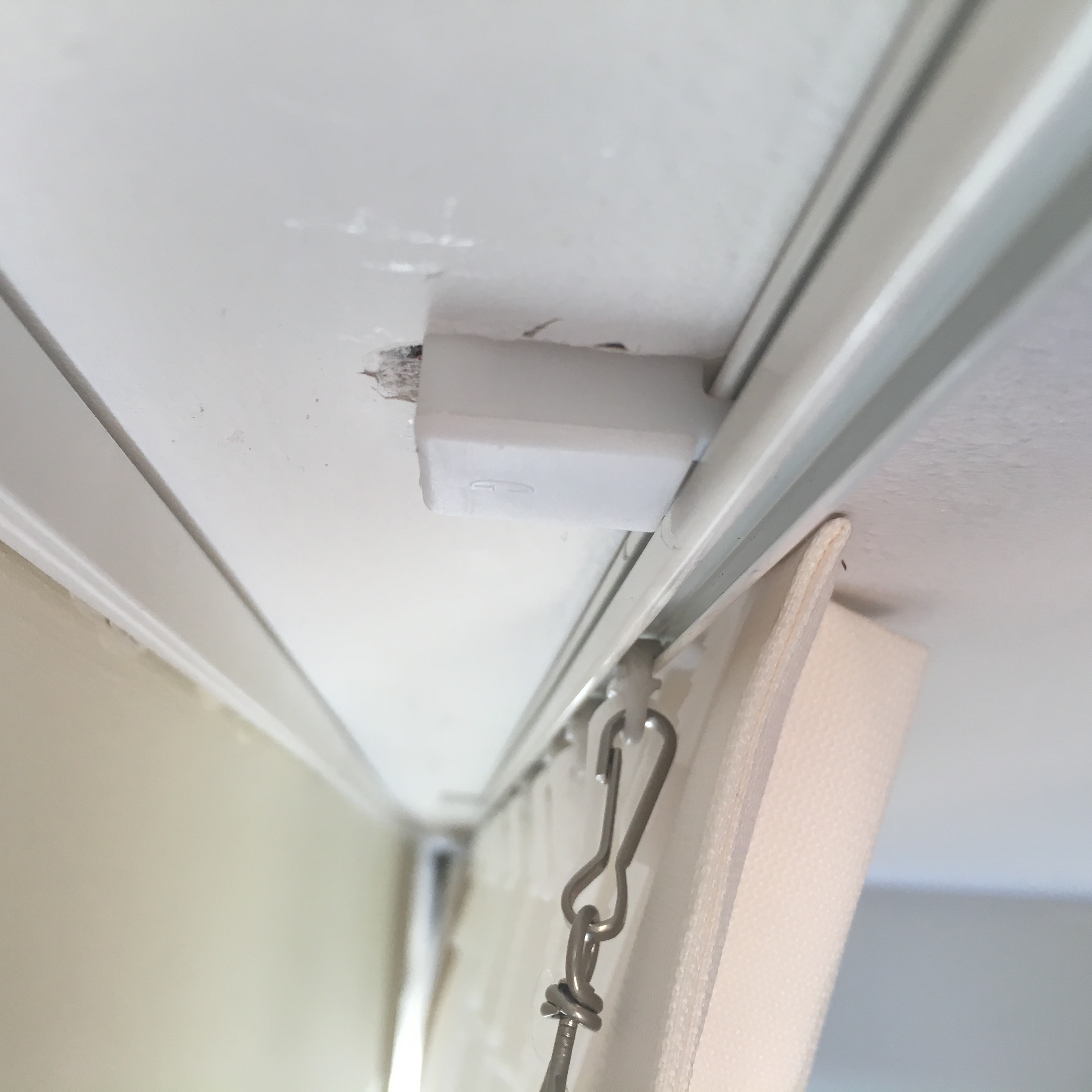
Of course this could easily be solved by printing some spacers, but to keep things compact, I’ve opted to mill some holes into the wood using a Dremel cutter.
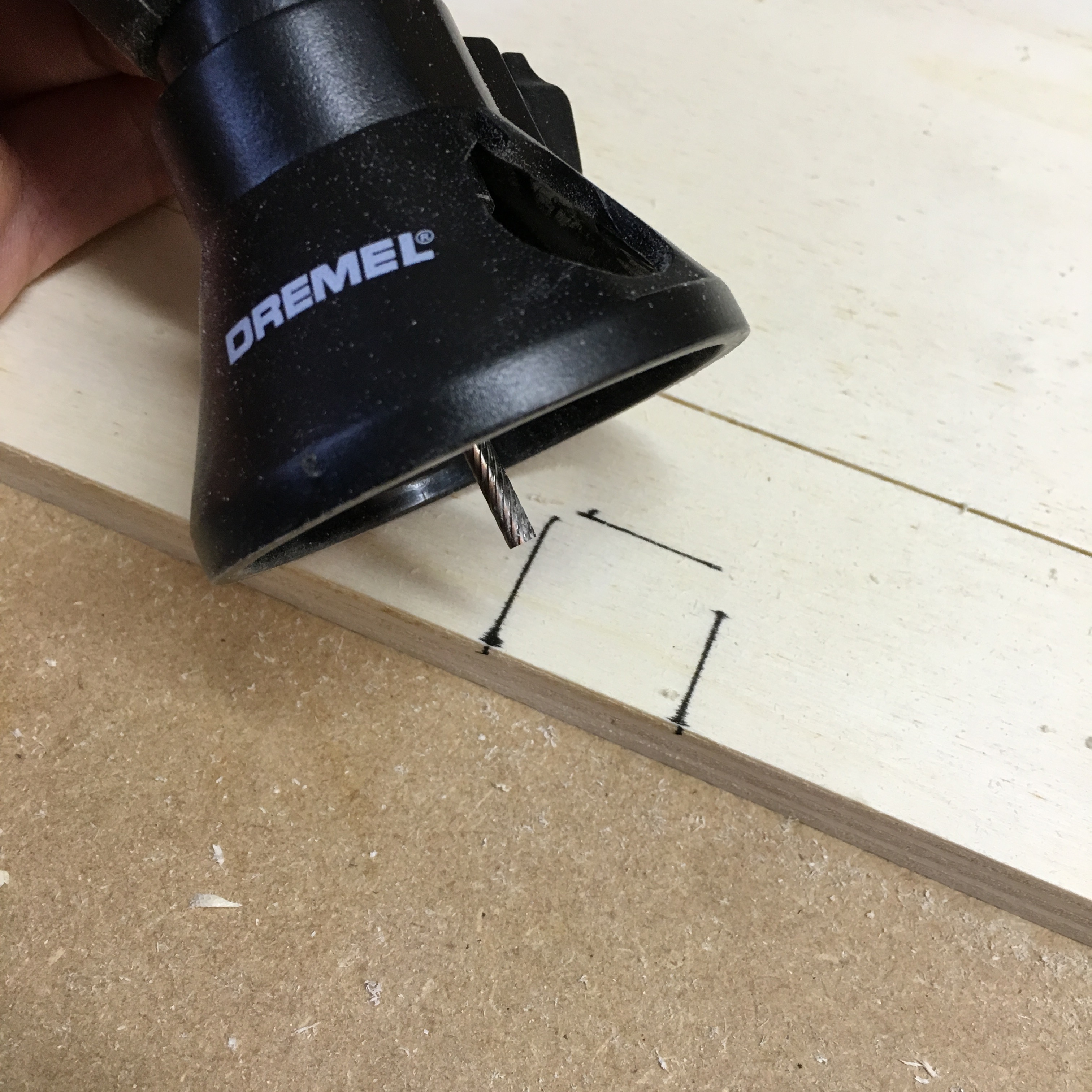
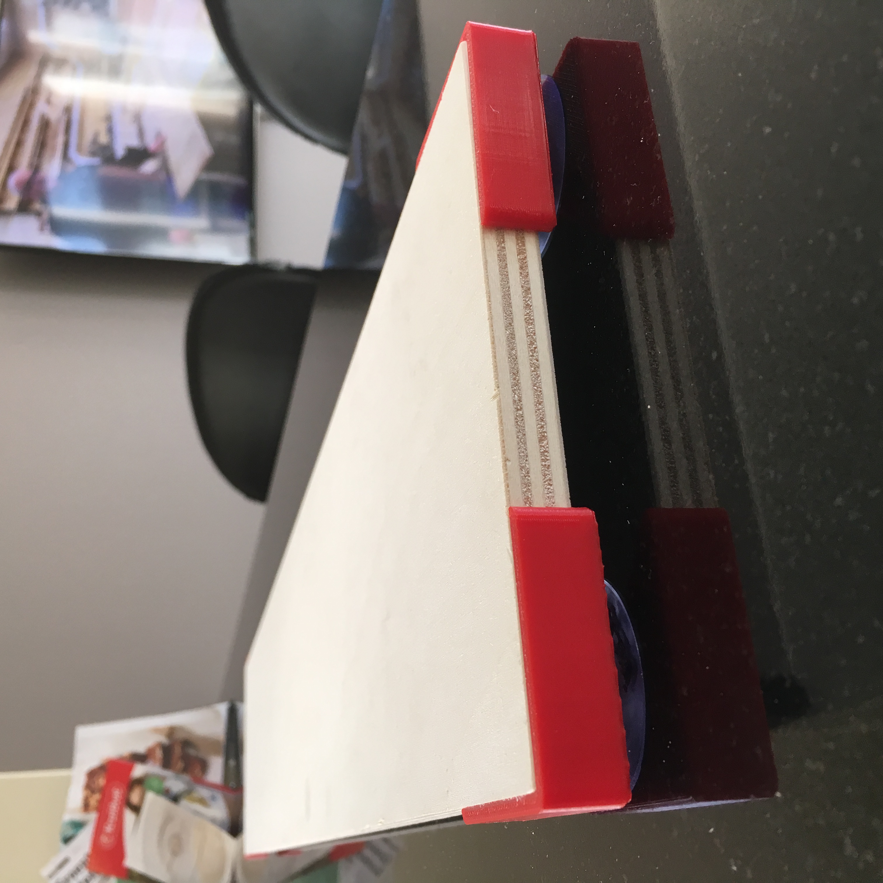
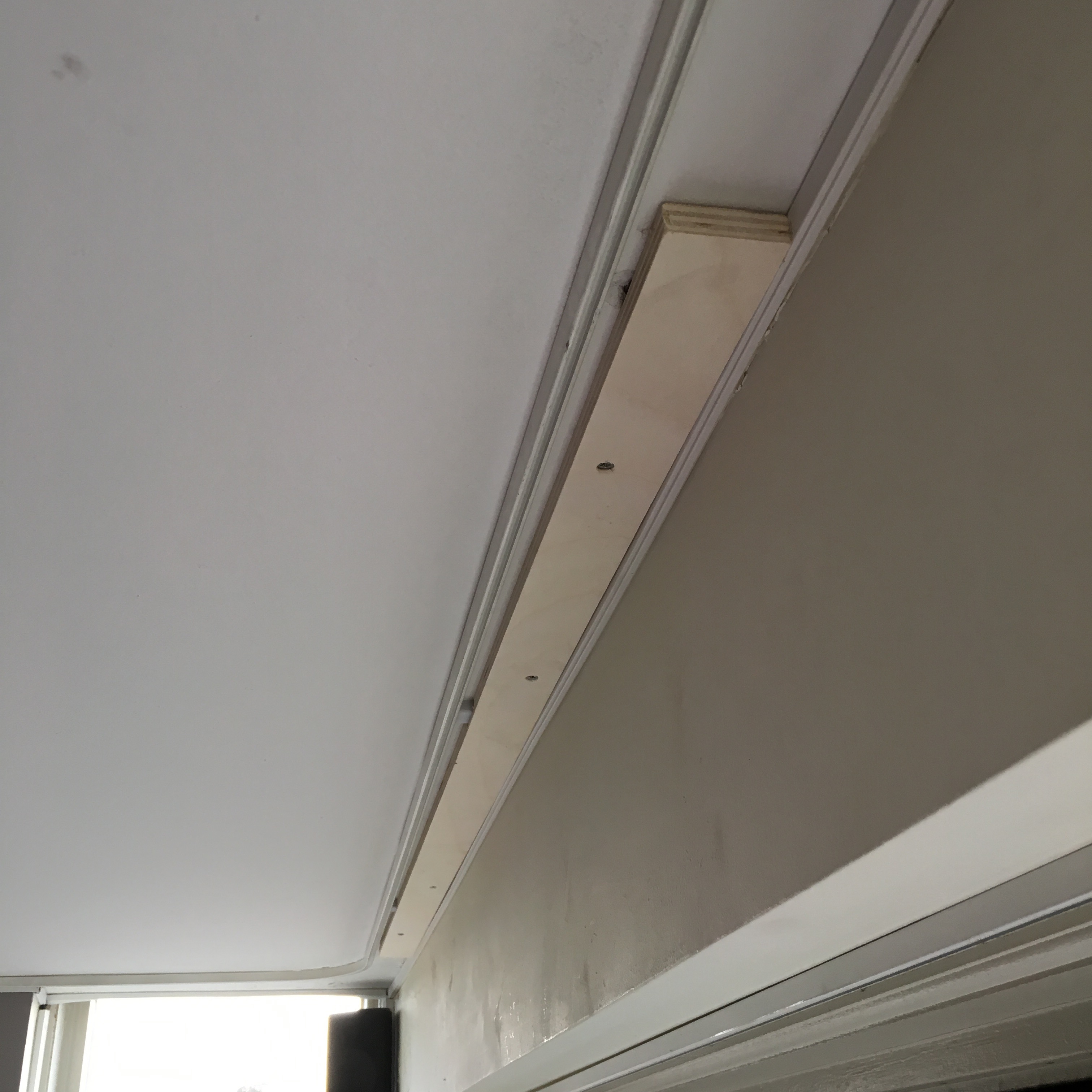
Practice makes perfect. So with a lot of patience, I’ve managed to produce my first perfect wooden base. To prevent split or warped wood, I’ve used plywood in stead of pinewood.
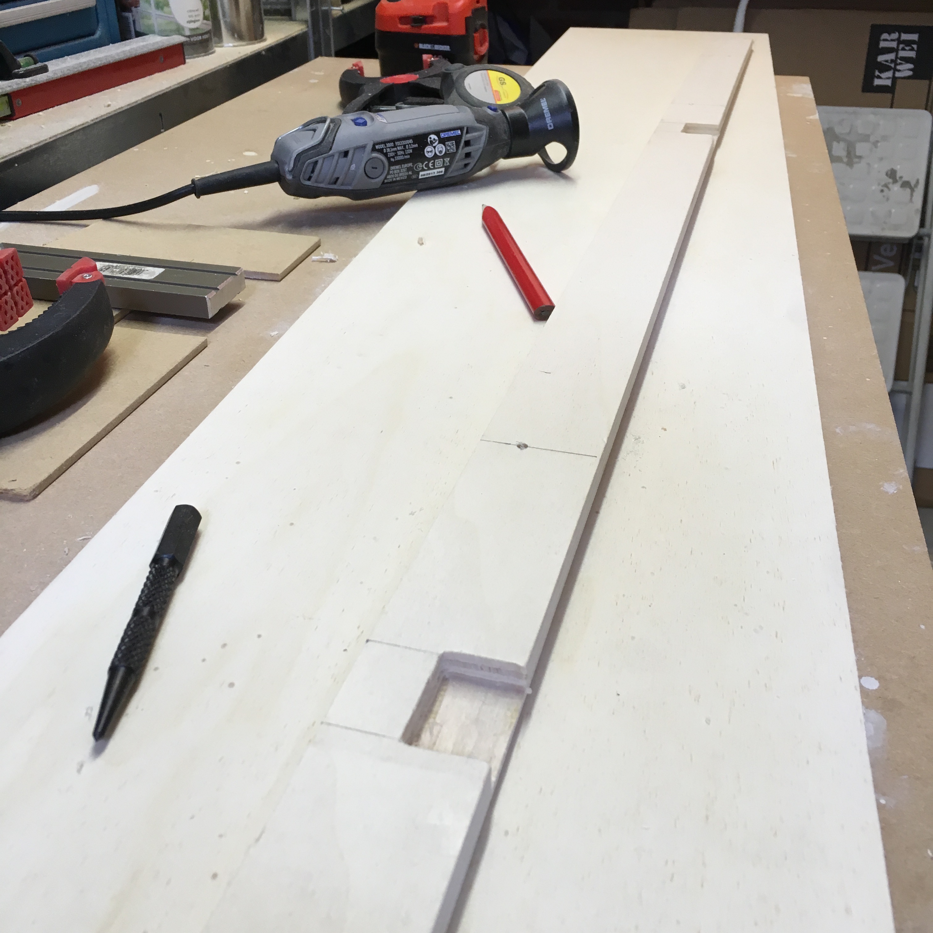
With the help of a dill and a lot of dust, the wooden base perfectly fits in place.
Four screws keep the base in place and allow me to detach the units for future maintenance.
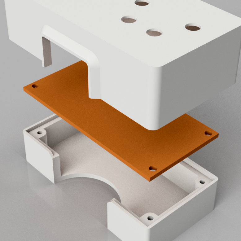
The motor mount
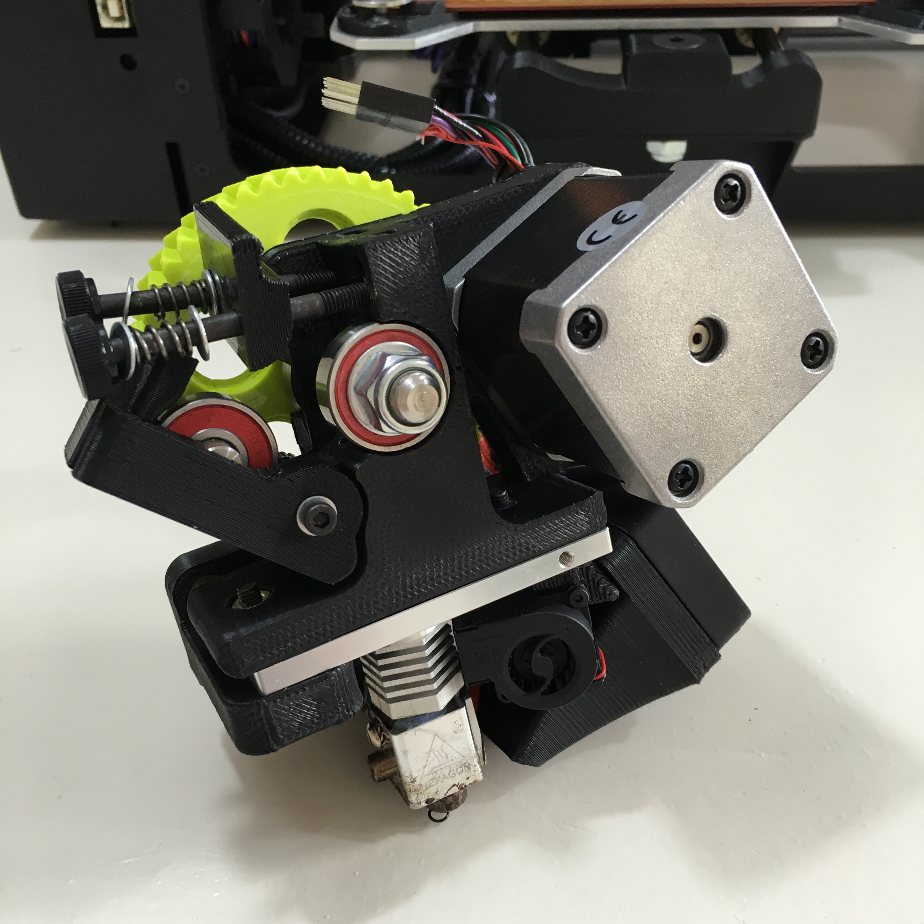
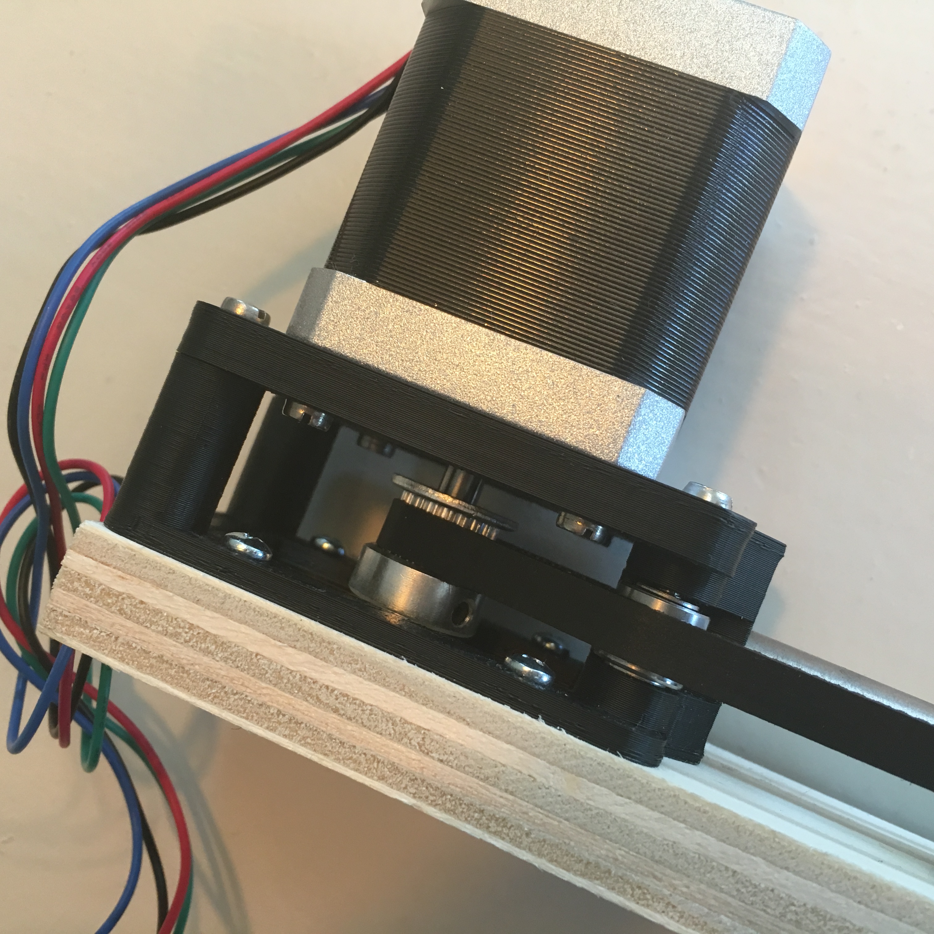
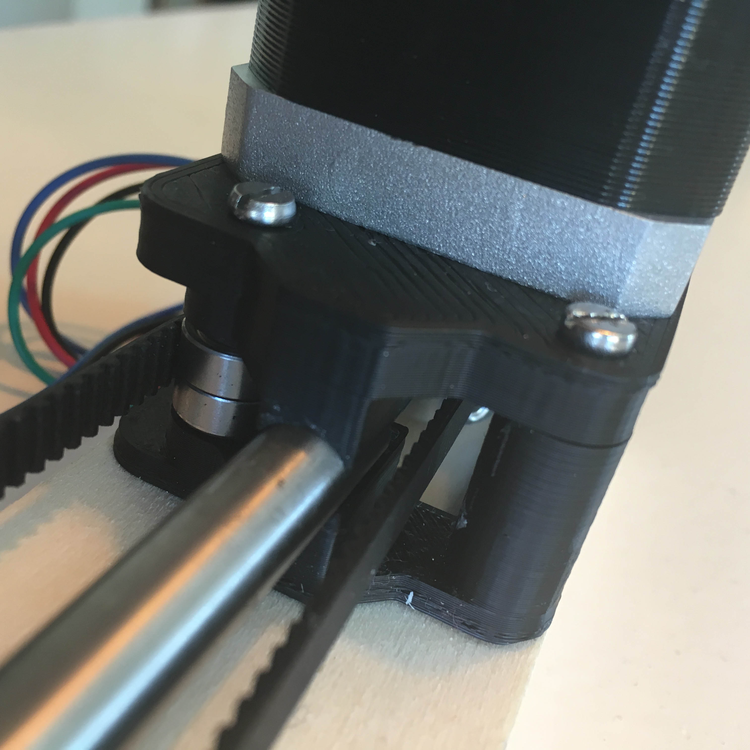
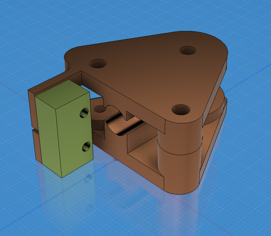
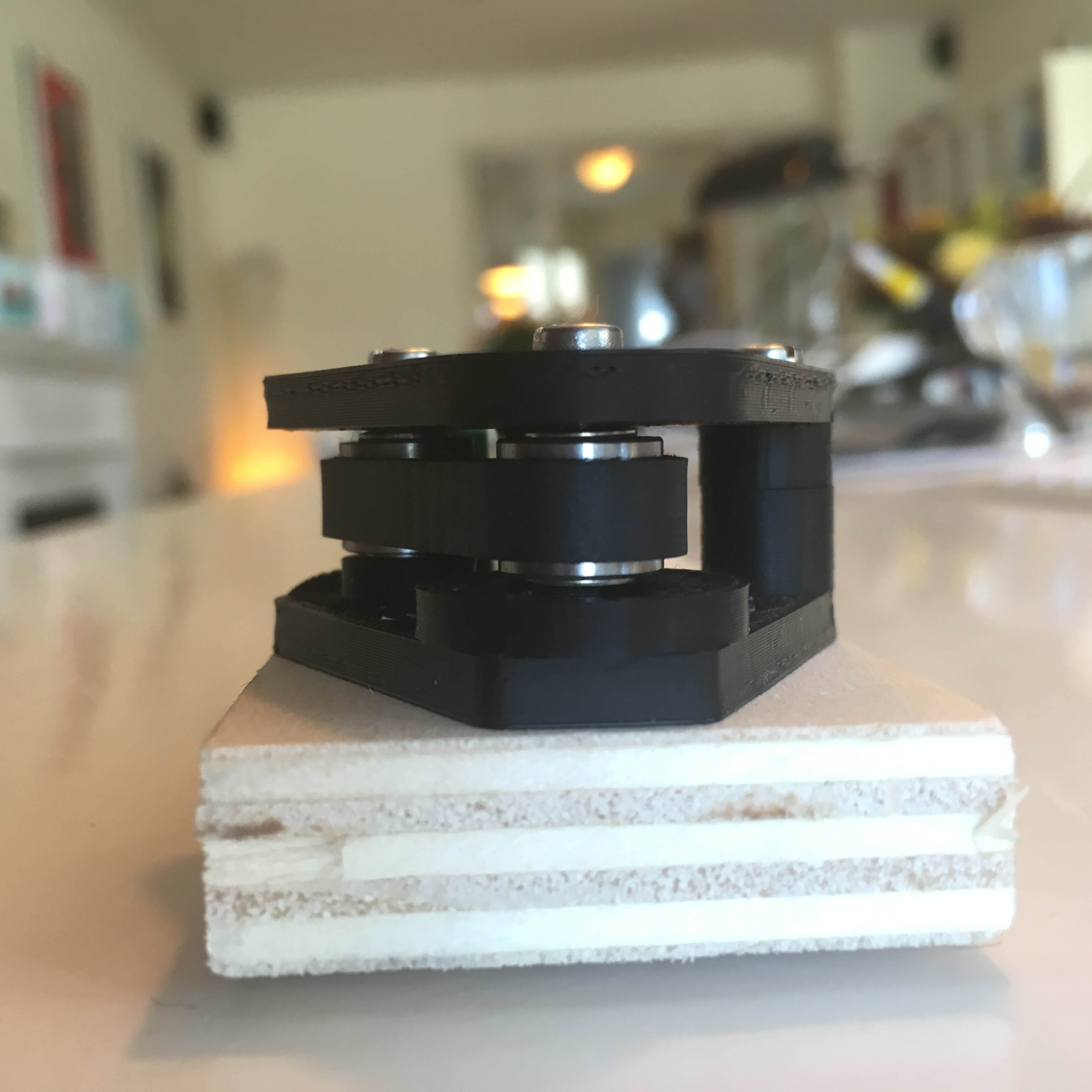
The first item to 3D print is the motor mount. It consist of 2 separate sections: a bottom which will be screwed onto the wooden base, and a top which will be screwed onto the motor. The two parts will be mounted upon each other which will also fix the 8mm steel rod in place.
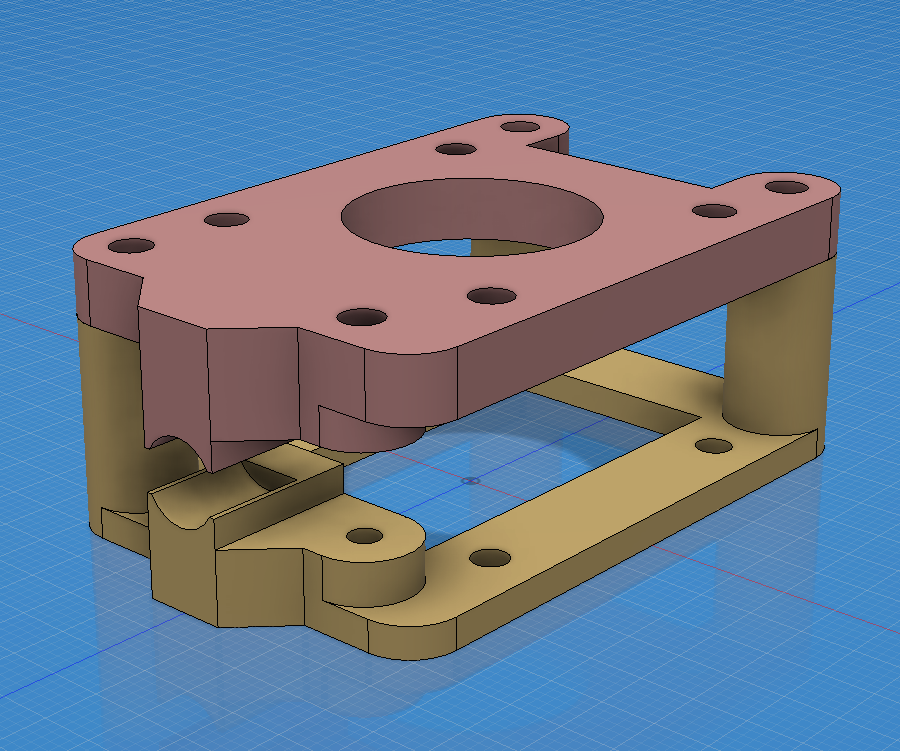
One side will get two 10mm ball bearings in between to guide the belt. Note that the mount photo below is a mirrored version of the illustration above, since these is a difference between the motor mount for the left curtain compared to the motor mount for the right curtain.

The top and bottom part are simply screw together using 3mm bolts. By printing 3mm holes, the bolts end up being self-tapping.
Want to get a better look at the motor mount 3D-design? Check out this link using Fusion 360’s awesome interactive preview.
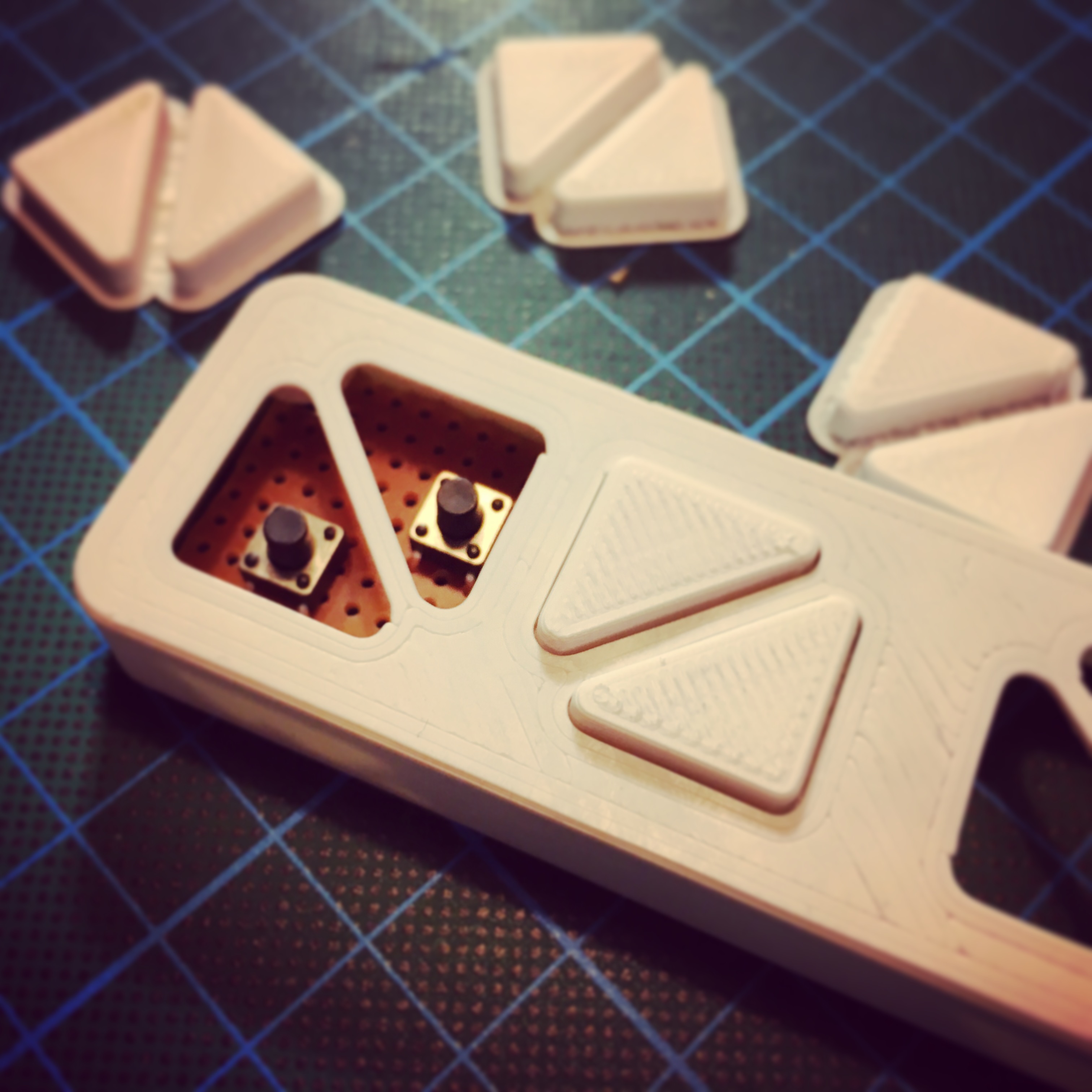
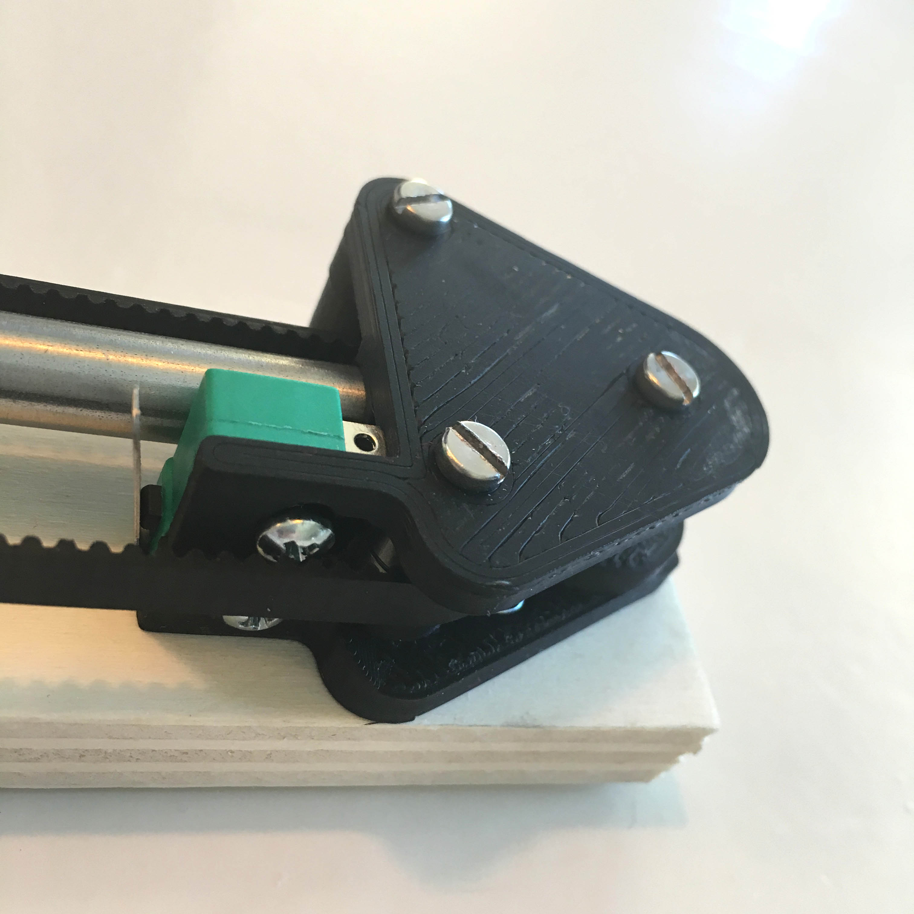
The end mount
On the other end of the 129.5cm long steel 8mm rod, a 3D printed end mount can be found.
The concept behind this mount is the same as the motor mount: it consists of 2 sections screwed together using 3mm bolts. The end stop contains 2 x 2 ball bearings to guide the belt around the steel rod.
Additionally, a micro switch is screwed on the end mount to be used as a non adjustable end stop. Once again, note that this 3d print is a mirrored version of the design above.
Want to get a better look at the end mount 3D-design? Check out this link.
The belt tensioner
To fix and tension the belt, a 3D-printed belt tensioner is used. Designing a tensioner can be a bit difficult, especially if you want to keep it compact. The curtain will be connected to the belt tensioner using a small 3d printed bracket. This is still on my to do list, though.
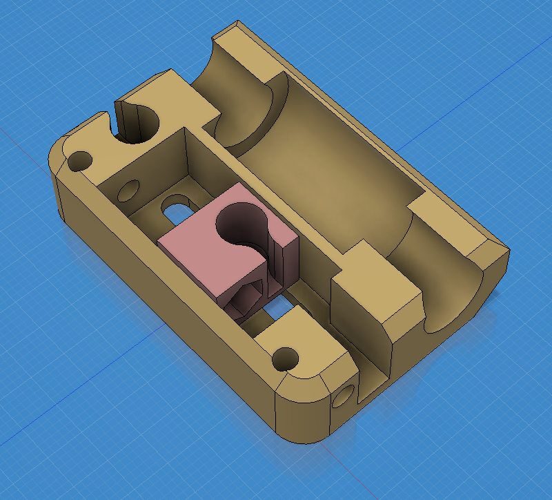
The belt tenstioner is guided along the 8mm steed rod using a lineair ball bearing snapped in place. The belt is fixed using 3 short 3mm bolts. A perfect way to allow future adjustment.
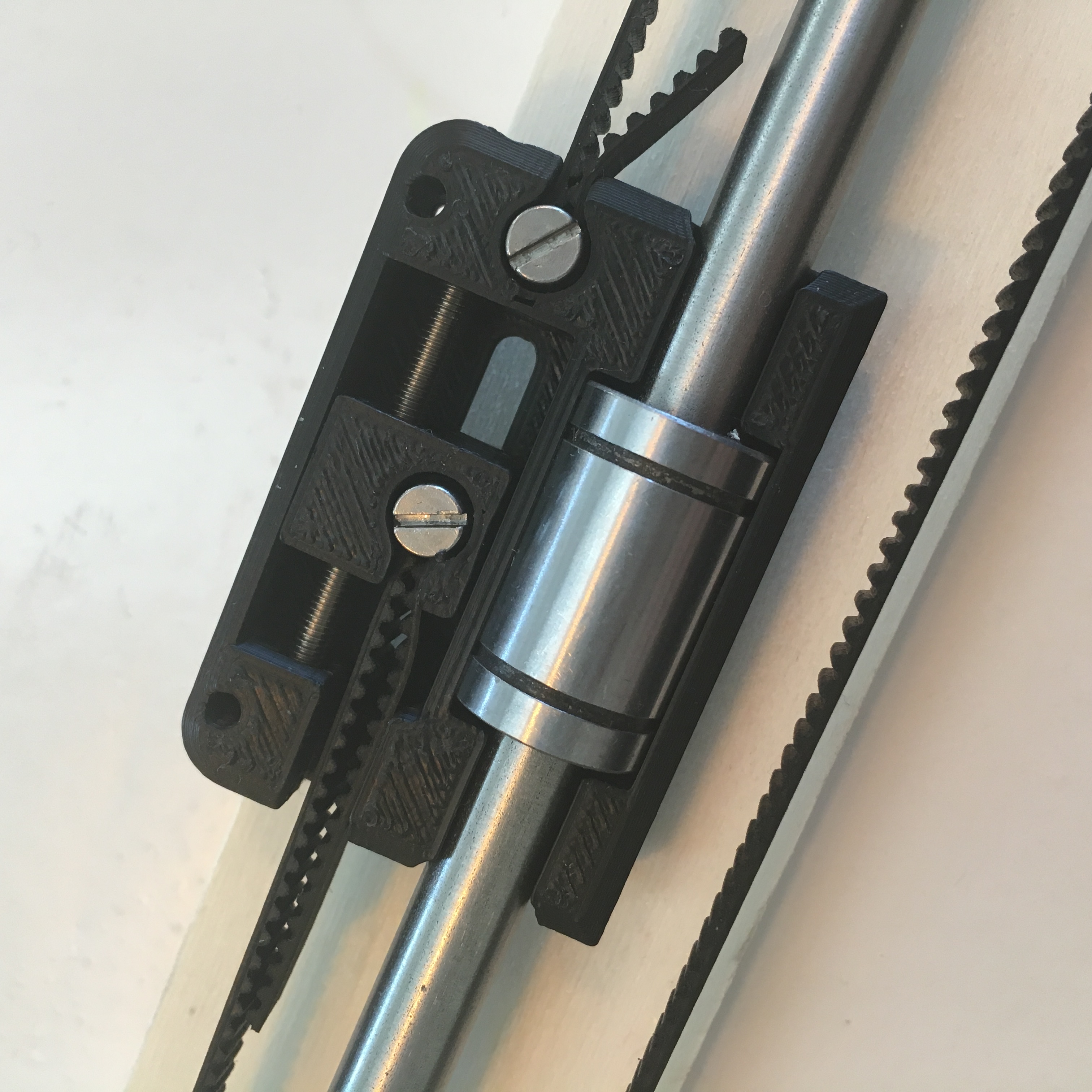
Using a 5cm long 3mm bolt, the belt can easily be tensioned by tightening the bolt. A 3mm nut fixed into the small block will simply pull the block to a tighter position. A system that works like a charm!
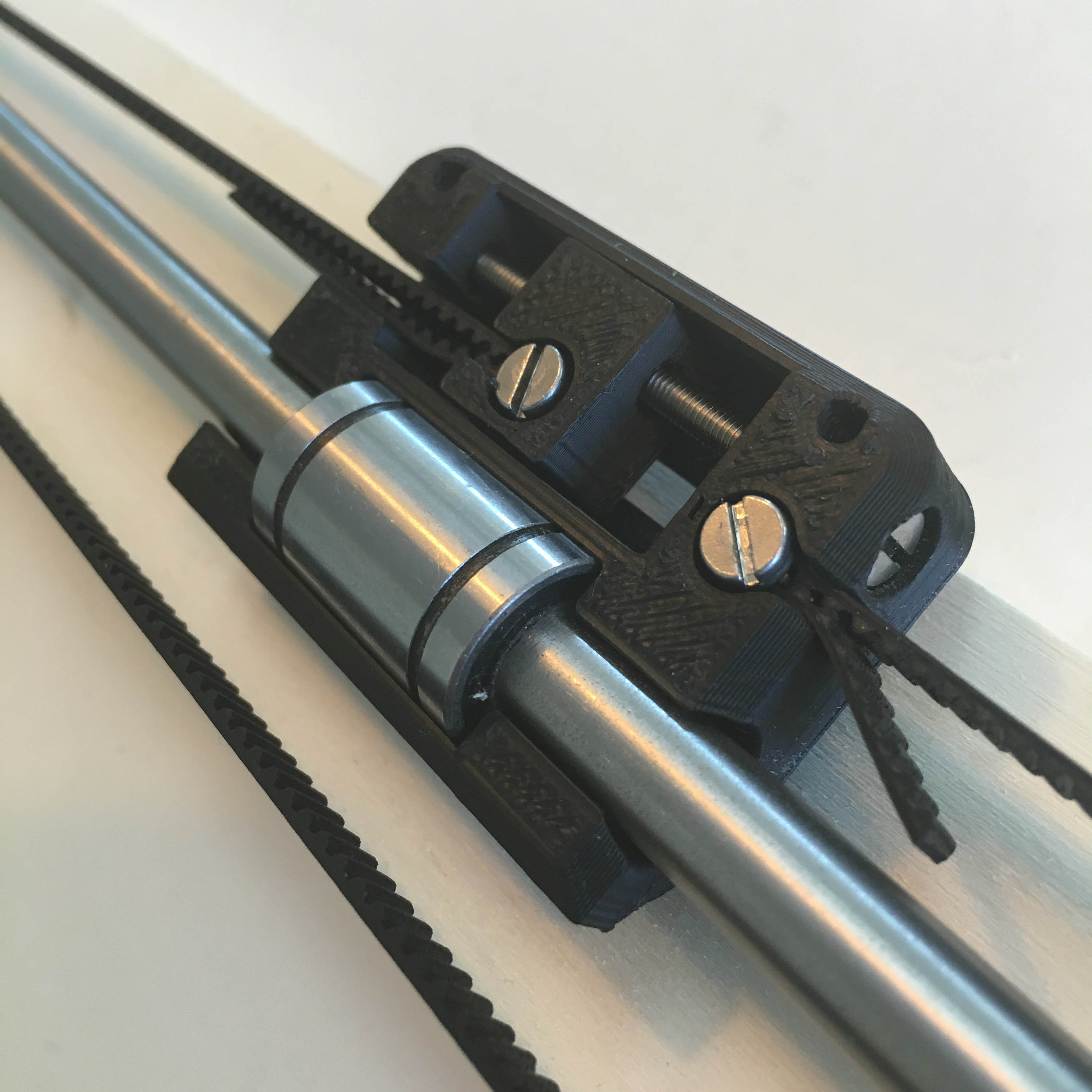
Unfortunately, the belt tensioner is currently still a little bit too large. To make sure I can built a casing around the motor units in the future, this is something I still need to address. A possible solution would be to off-center the steel rod. But this would affect all of the parts. Redesigning only the tensioner is complex but probably the best route.
Want to get a better look at the belt tensioner 3D-design? Check out this link.
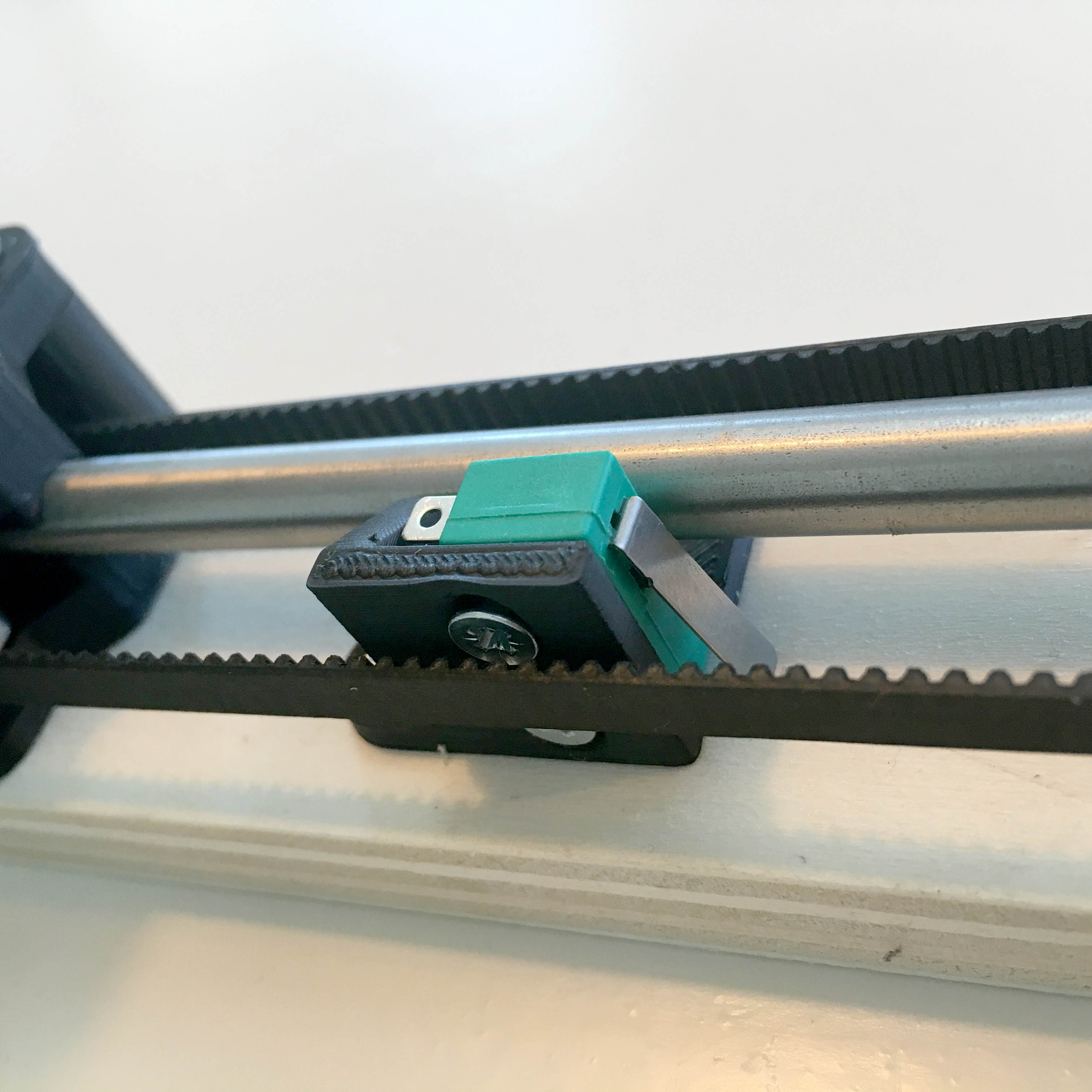
The adjustable end stop
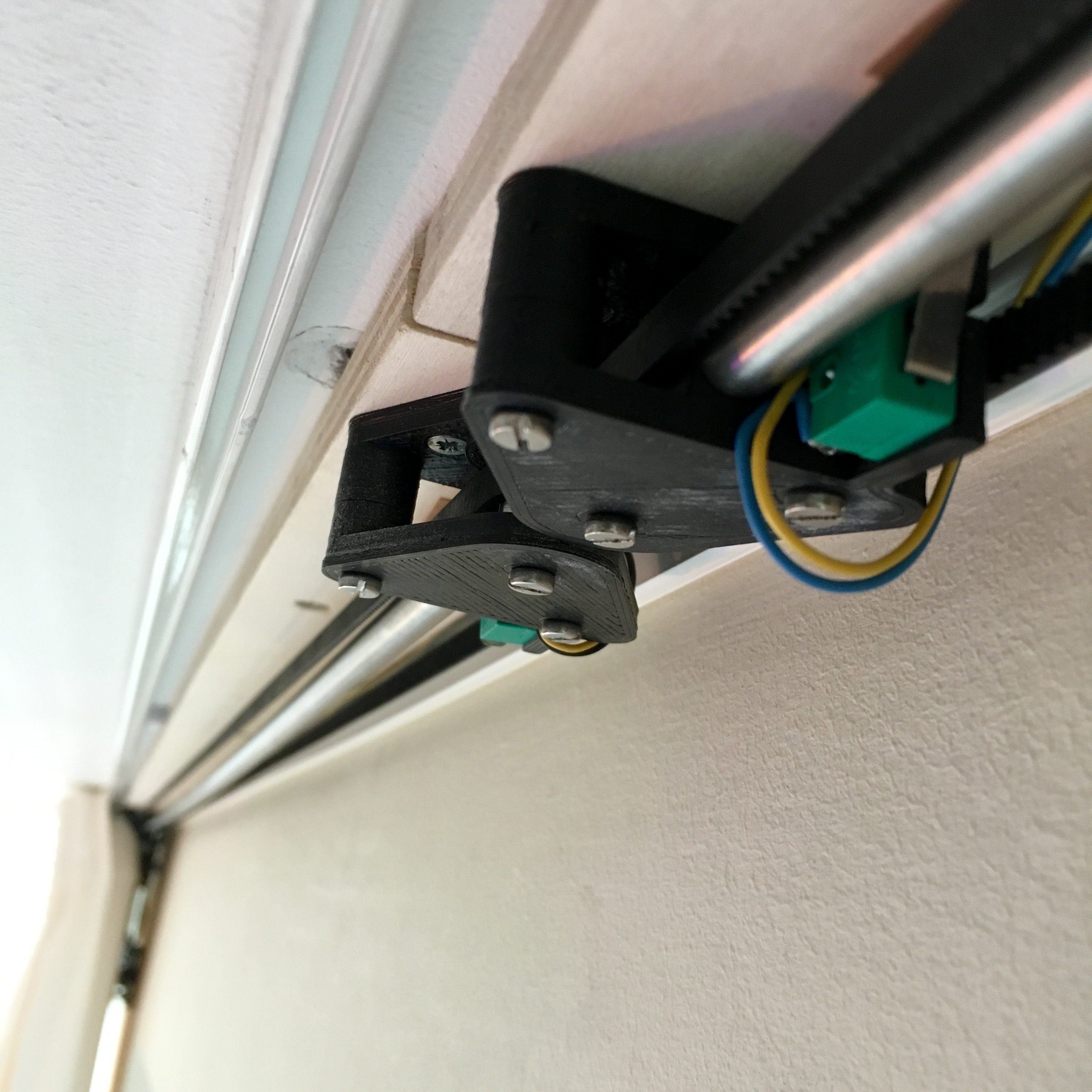
On the motor side of the steel rod, an adjustable end stop switch is kept in place using a small 3D-printed mount.
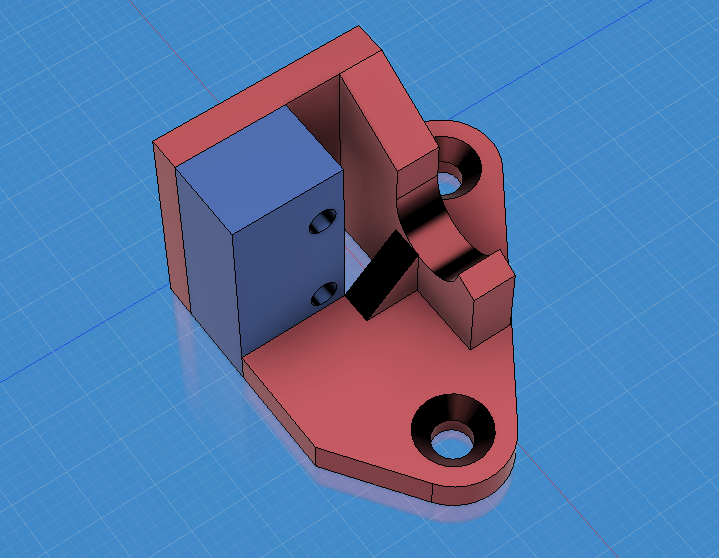
Four recessed self-tapping screws keep both the switch and the mount in place.
Want to get a better look at the adjustable end stop 3D-design? Check out this link.
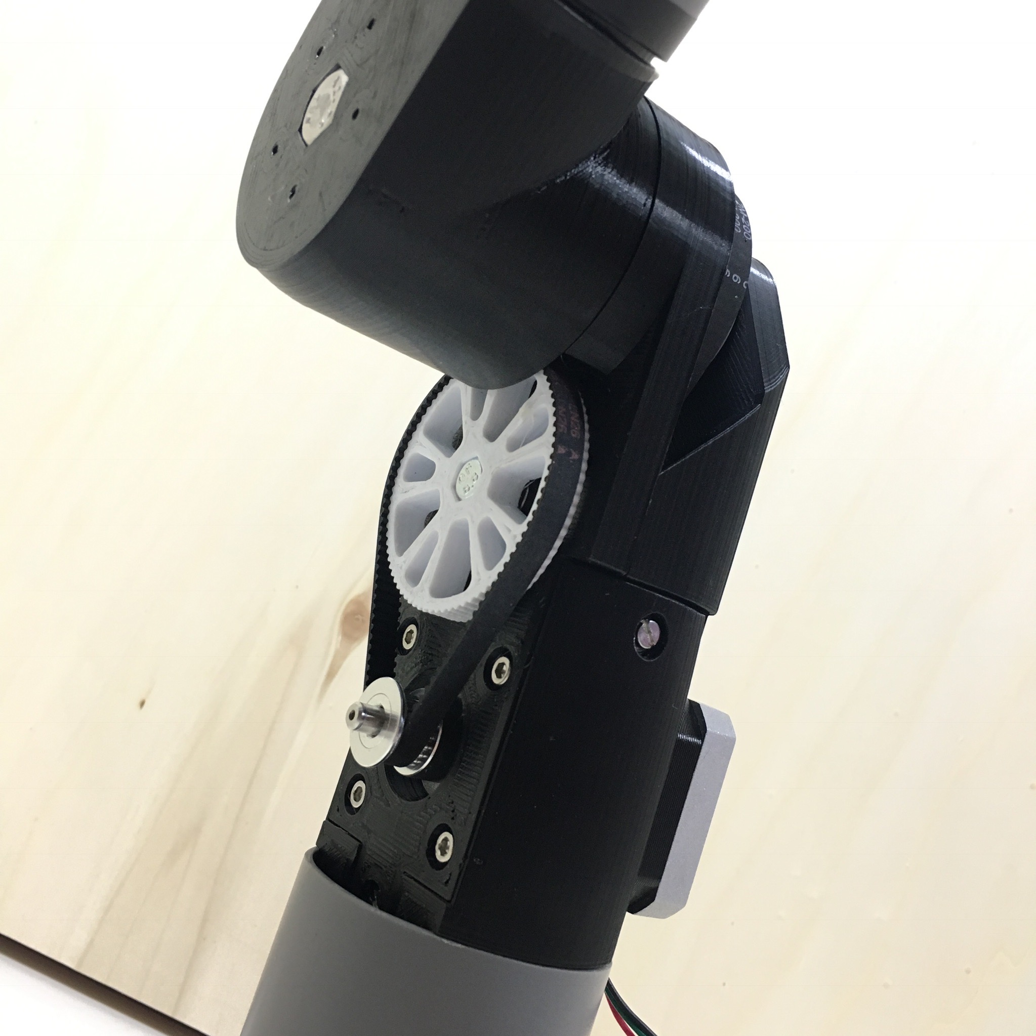
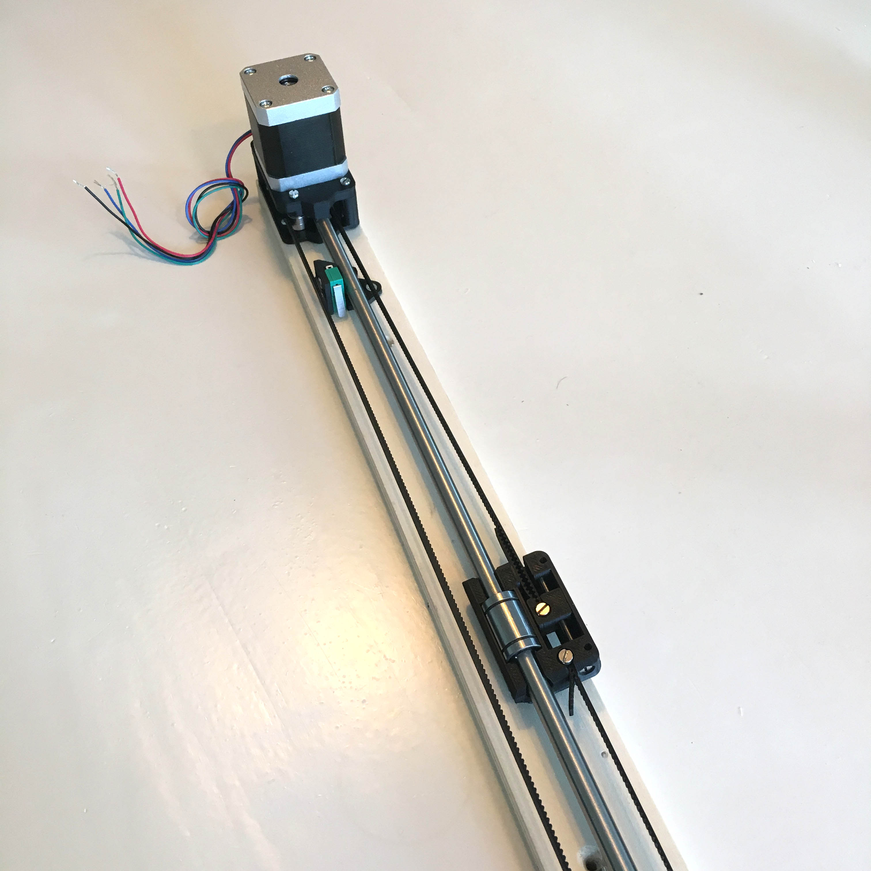
The end result
The end result is a motor unit ready to be screwed to the ceiling behind the curtain. Of course, the electronics still need to be implemented, and the end stop switches still need to be connected. But for now, it’s a satisfying end result.
Any ideas how to make the belt tensioner more compact? Leave a comment down below!
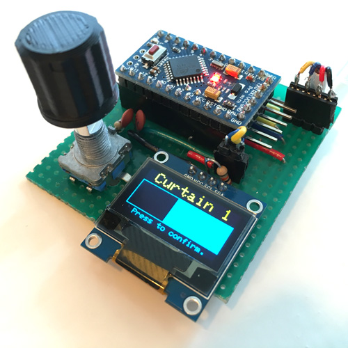
Automatic Curtains: Take control!