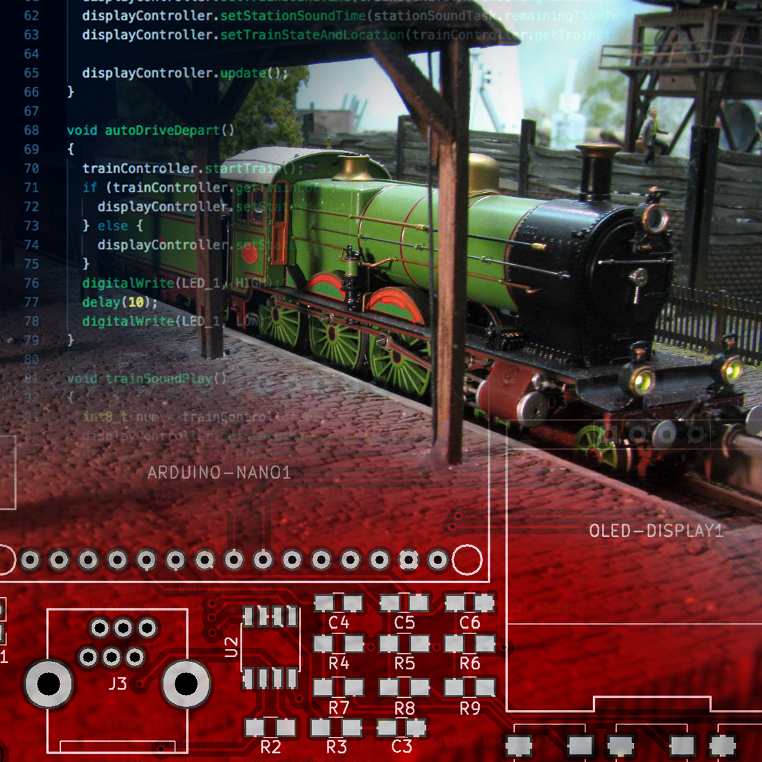
As my regular readers know, my dad is an avid Model Train hobbist. And altough my interest is more on the digital side of electronics, every now and then our hobbies meet. After my recent Arduino powered analog clock project, I once again will work on a project for my dad: Let’s make his trains Arduino powered!
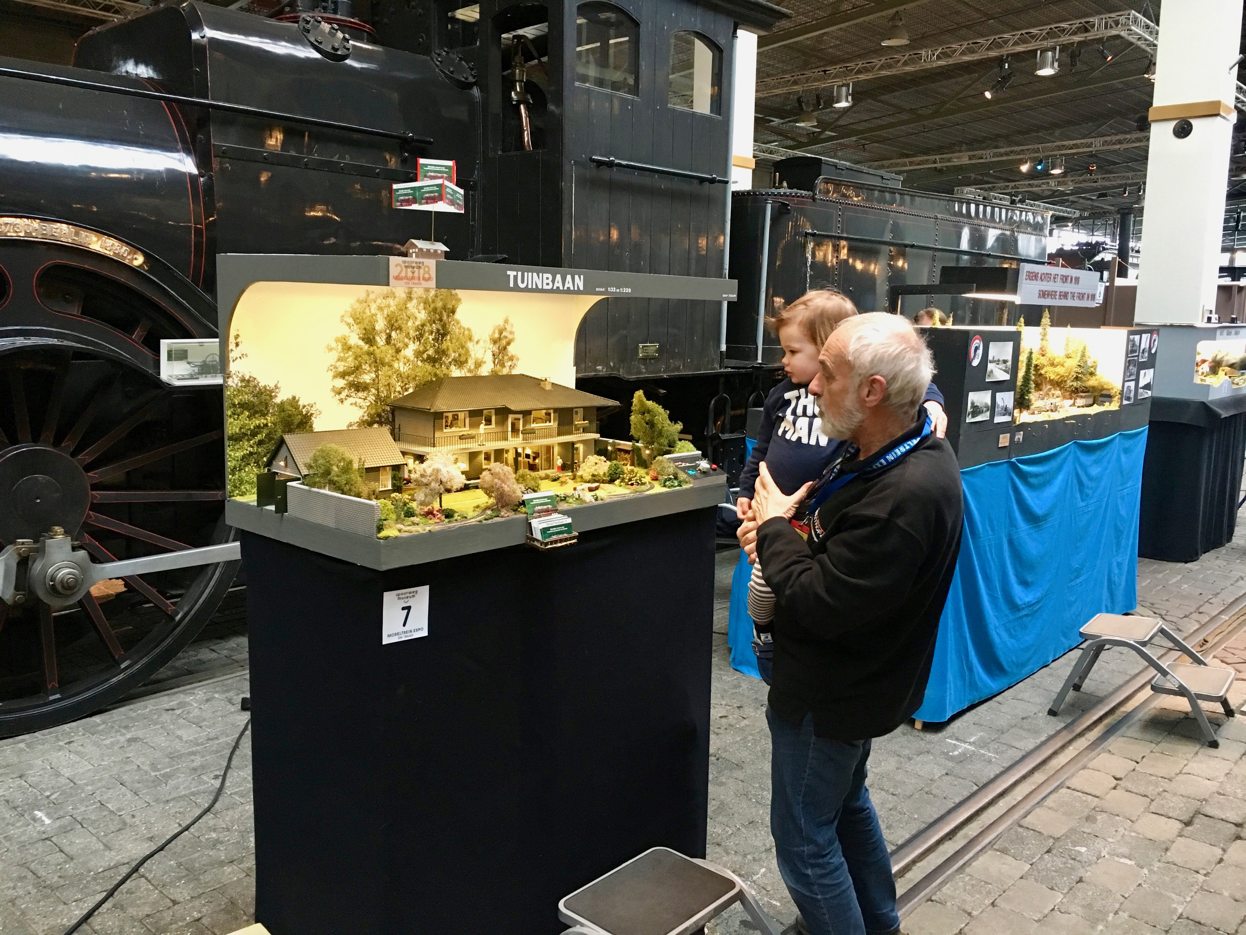
In the past years, my dad’s train artworks were featured during the OnTrax Train Expo in the dutch Railway museum. The photo above (which show my dad and my oldest son Enzo) is made during the most recent expo and features the train controller I built last year. During the next Expo, my dad will show his new creation with a shuttle train.
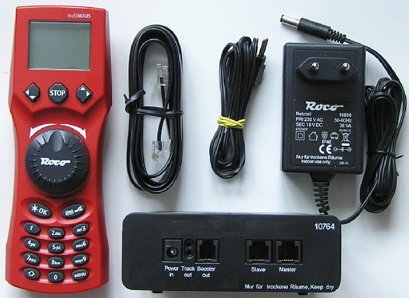
Like most of his tracks (with exception of the track in the previous picture) the shuttle train will be controlled using a Roco MultiMAUS and although this allows for very easy control, this would mean he needs to continuously operate the train during the expo weekends. Of course there are many automated solutions to solve this. Unfortunately most of them are pretty expensive, complicated and would require my dad to connect a full blown computer to the track.
As an enthaustic microcontroller fanboy, I’m sure I can come up with a simpler solution that allows him to automate his shuttle train.
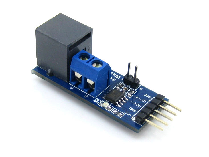
The MultiMAUS is connected to the track via a digital amplifier. The digital amplifier and and MultiMAUS use the RS485 protocol to communicate which can be connected to an Arduino with the help of a MAX485 IC. To make life a little easier in the prototyping phase, I bought a Waveshare 485 breakout board.
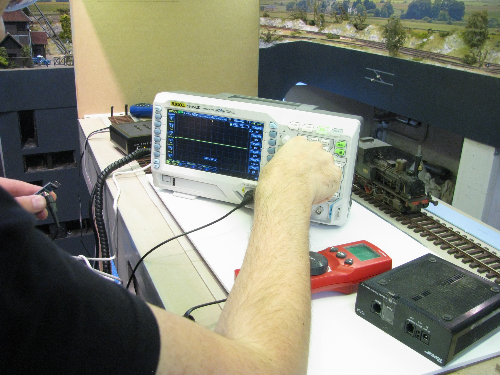
To check if I was on the right track (pun intended), I hooked up my Rigol DS1054Z oscilloscope to see if I indeed receive some data …
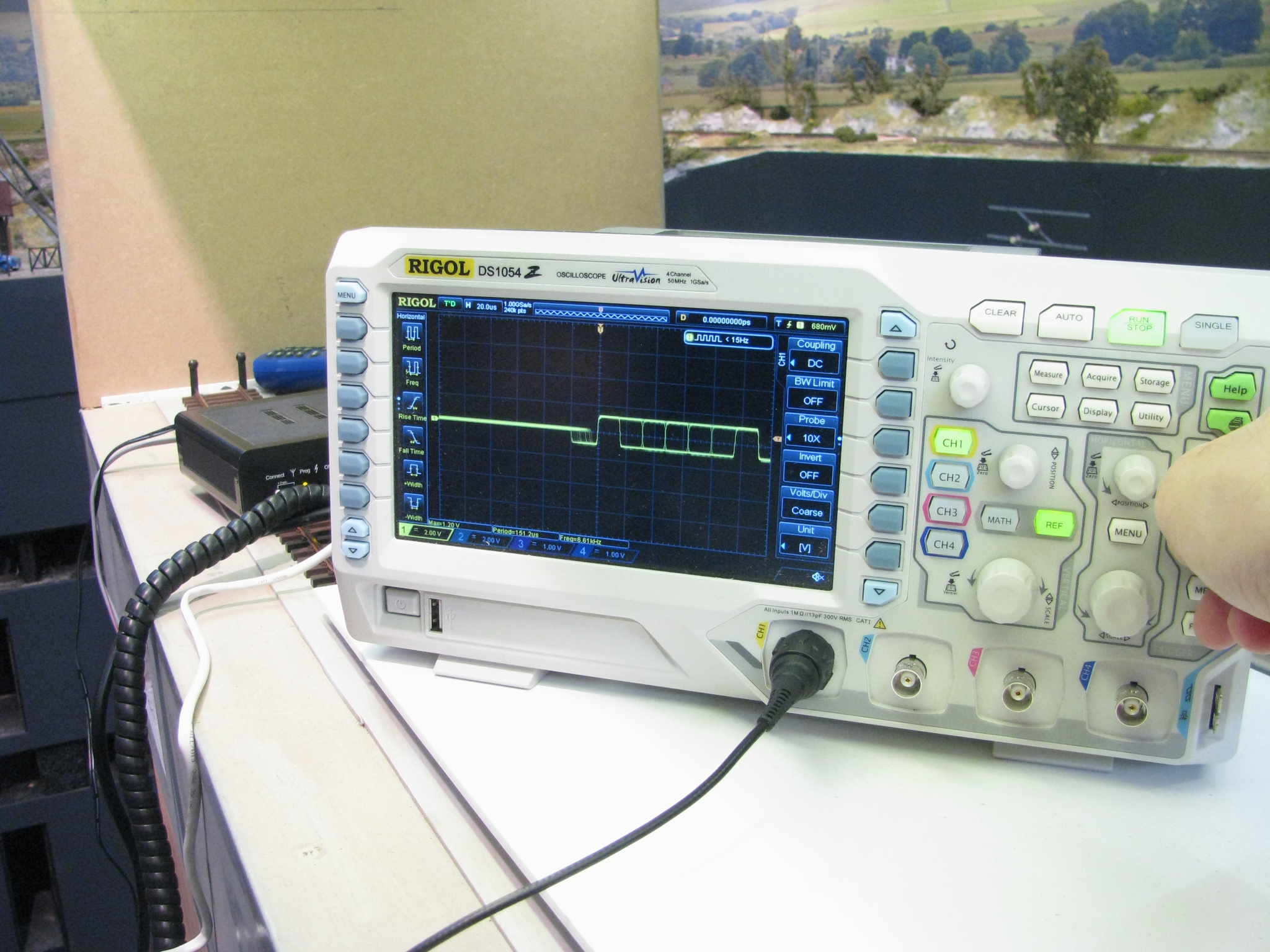
And after some fiddling around and swapping the A & B channels on the bottom of the MAX485 breakout board, I the bits started to appear on my oscilloscope. Great!
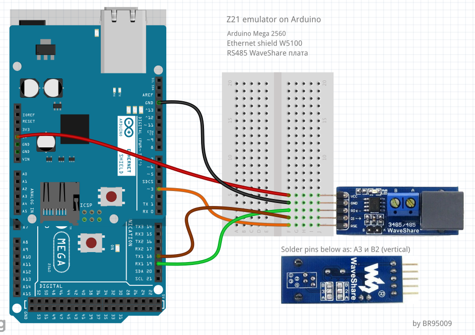
Of course, I wasn’t the first person to start this adventure. As a matter of fact, I couldn’t have done it without the help of Philip Gahtow who wrote the awesome XpressNet library. This library also included the image above which shows the wiring needed for this project.
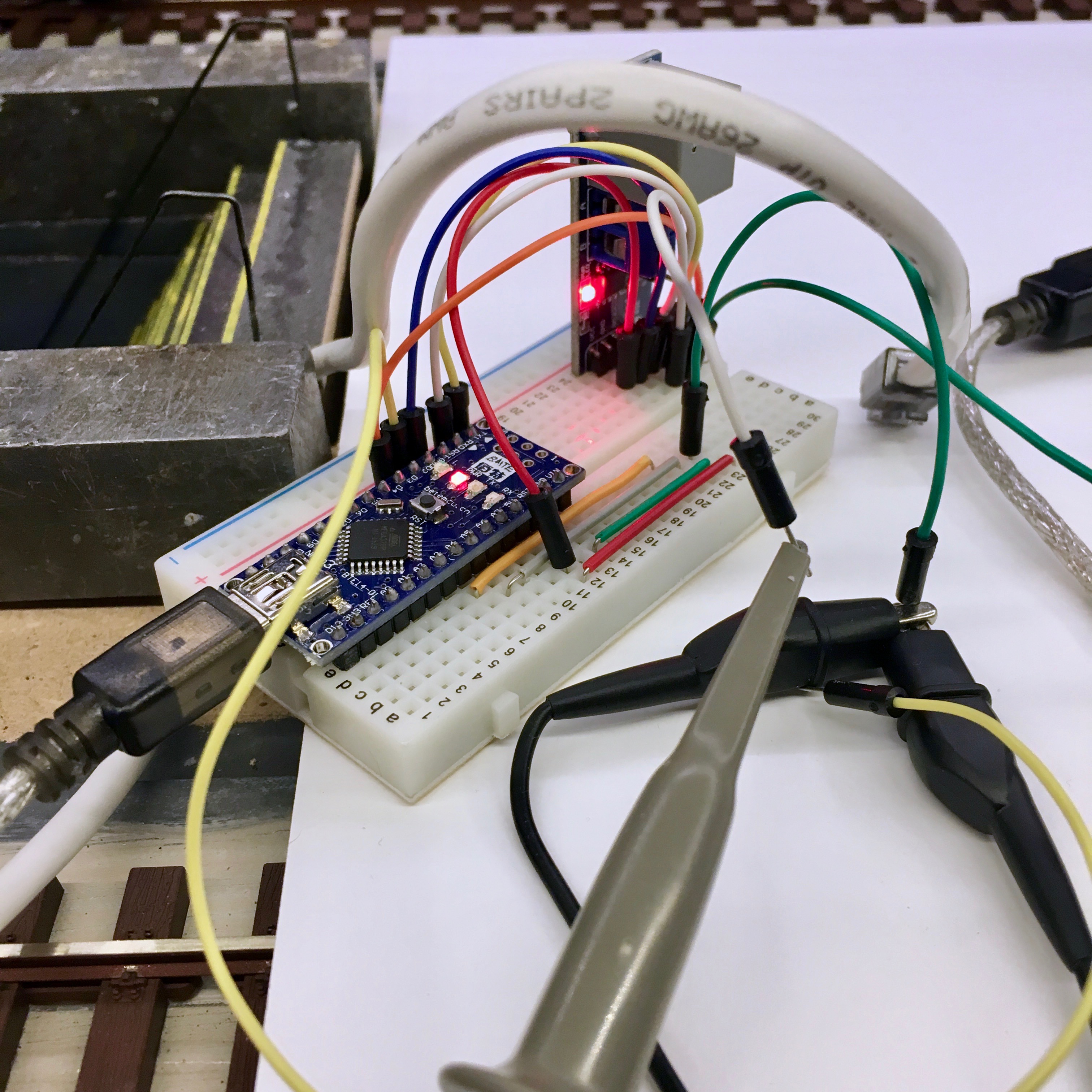
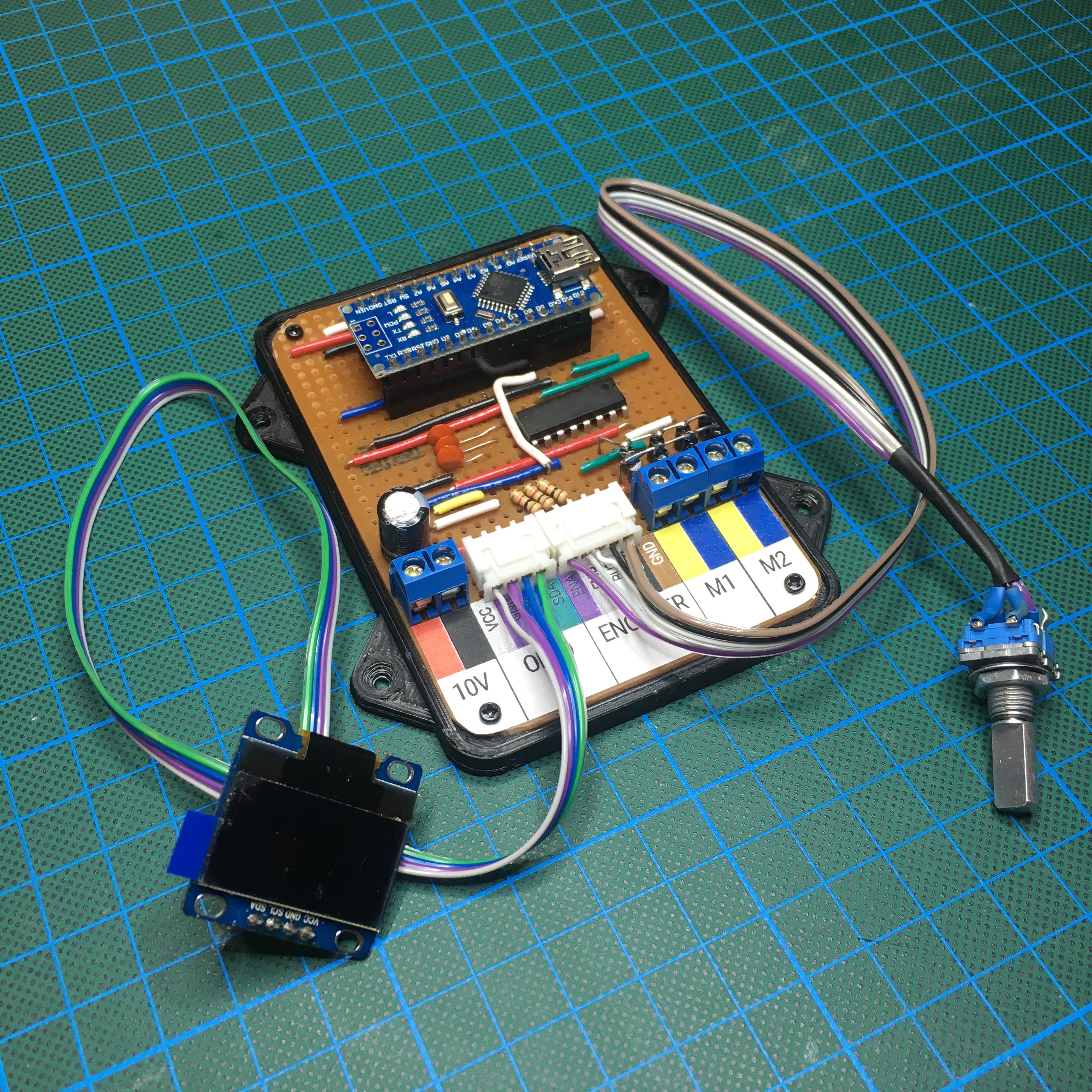
Since I’ll be using an Arduino Nano which only has one Serial port, there was one caveat: I couldn’t flash the Arduino while it was connected to the RS485 bus. But with that in mind, wiring everything up was pretty straight forward.
Of course, the system also needs a way to detect if the train approaches the end of the track. And although there are many (complicated) ways to achieve this, I will go for the easiest solution possible: adding a magnet below the train, and putting two reed contacts between the tracks. For now (since we are prototyping) I just manually control the end stops by connecting the yellow wire to one of the two assigned end stop pins of the Arduino.
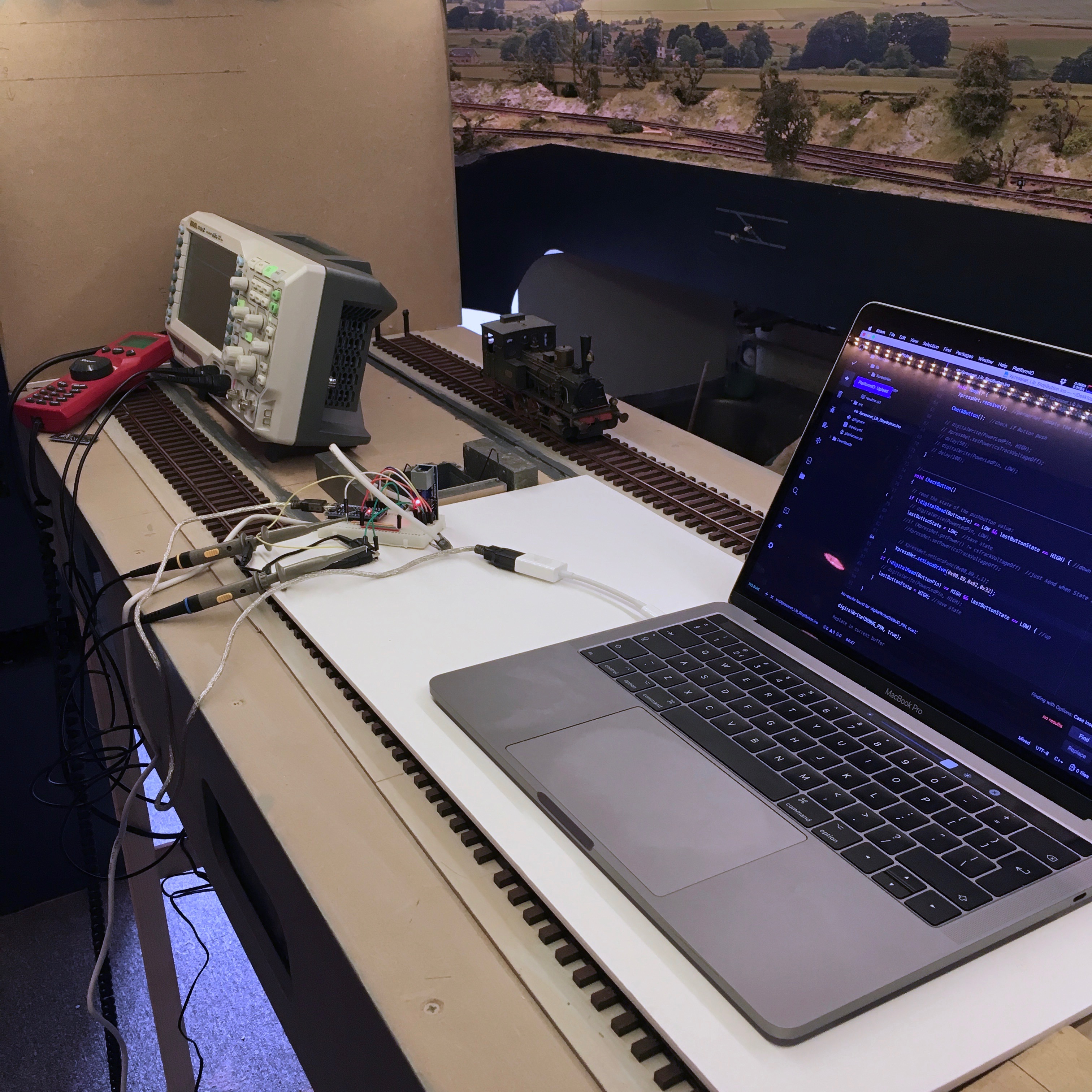
And with the electronics all wired up, it’s time to start working on some proof of concept code. I must admit it’s a pretty unique place to do some coding: right between the tracks.
Let’s see if we can start the trains.
First, we need to set up the basics:
// Include the XpressNet Library
#include <XpressNet.h>

// Define the address we will be using for our virtual MuliMAUS.
#define XNetAddress 31

// Define which pin we use to enable the transmission to the digital amplifier.
#define XNetSRPin 3

// Define the ID of the train we will be talking to.
#define TRAIN_ID 89

// Create an instance of the XpressNet class.
XpressNetClass XpressNet;
Next, we need to configure the XpressNet object, and finally we can give the train the command to start driving. In this prototyping phase, let’s keep it simple, and put it all in the setup() routine, so this command will be only be given once.
void setup() {
    // Initialize the XpressNet controller, using the defined values.
    XpressNet.start(XNetAddress, XNetSRPin);

    // Queue the command to start the train.
    XpressNet.setLocoDrive(0x00, TRAIN_ID, 0x13, 32); // Speed: 32
}
Note that It said the command is queued. It won’t be send to the train directly, since the XpressNet library will wait for data from the digital amplifier first. This is something that took me a while to find out, but luckily, the solution is very simple. We need to call XpressNet.receive(). in the main run loop:
void loop() {
    // Check if there is anynew data available, and then send all queued messages.
    XpressNet.receive();
}
And low and behold, after uploading the code and connecting the MAX485 unit to the digital amplifier, the train starts moving!

A few caveats I ran into:
- The acceleration and deceleration of the train is something that is programmed into the train. It is not something you can control on the fly. We need to take this into account when we place the reed contact end stops.
- The speed is a one byte value (0-255). Everything below 128 is forward driving, 128 and up is backwards driving.
- As said: we need to listen for new data before our commands are send.
And with that in mind, we can start working on the read deal.
Of course my dad likes to give me a nice challenge. So not only are we going to control the train’s movement. We are going to add the following as well:
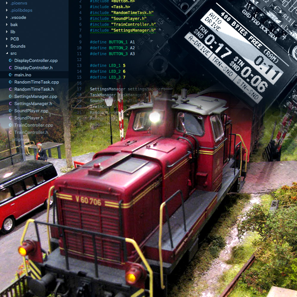
- An OLED display to see the current state of the train and the time of the next automated departure.
- We are going to control the on board train sounds (literally: bells and whistles).
- We will add an integrated MP3 player to add train station sounds that are played at random intervals.
- Everything is going to be configurable using a few integrated buttons to allow my dad to change the intervals without the need of a computer.
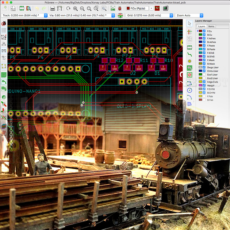
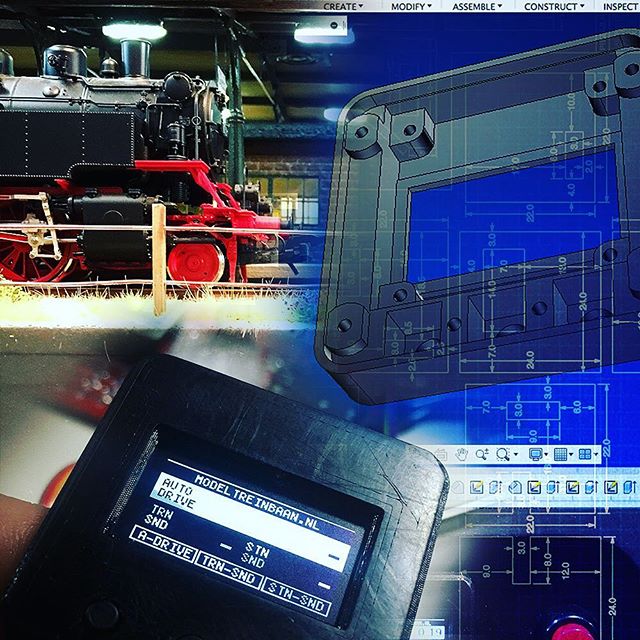
Of course, I can’t just hand over a breadboard contraption, so in the next post we are going to work on a custom designed PCB that houses all the necessary electronics. Read it here!
Train Automator: Designing the PCB