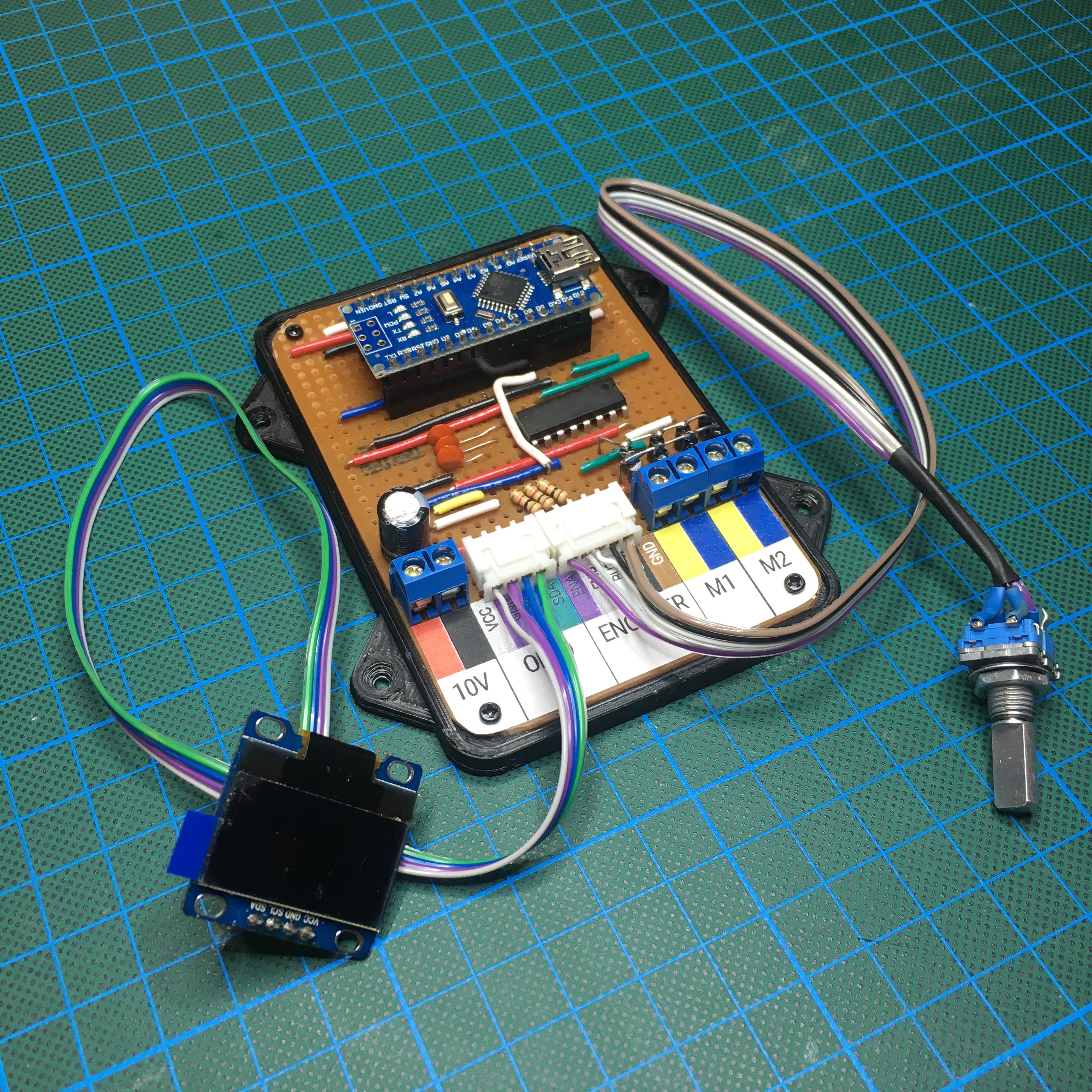
Since the prototype turned out to be a success, it is time to work on a more professional solution: a custom PCB. Of course I don’t just slap an Arduino and a MAX485 IC on a board and call it a day. I use this opportunity to add some nifty features to the custom board. You know, just to impress my dad.
Train Automator: Prototyping
The train my dad is controlling has on board sound. But just as in real life, it’s not only the train that makes sound. By adding a MP3 player to the board, we can play random sounds over a train station speaker.
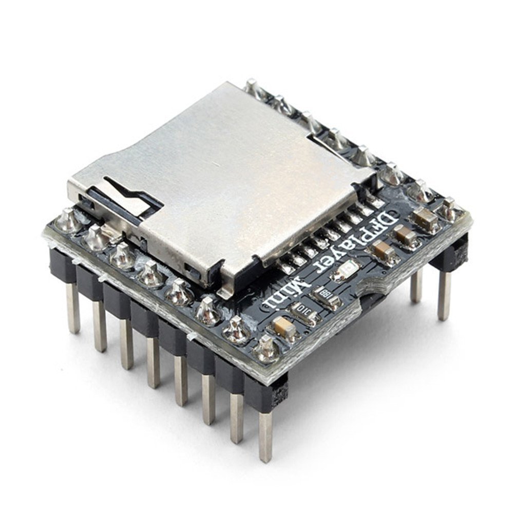
For this project I use a DFPlayer Mini. A $1.50 MP3 player with integrated (mono) amplifier. It uses Micro SD cards to store the sound clips and can be controlled over a UART serial interface (together with many other control options).
I have a soft spot for tiny displays, so whenever a built a project like this, I find a way to integrate a display. The display is just as cheap as the DFPlayer Mini, so I think I can justify the costs.
Now, of course sound and display won’t be enough to make it a stand-alone controller. So here’s the full feature list:
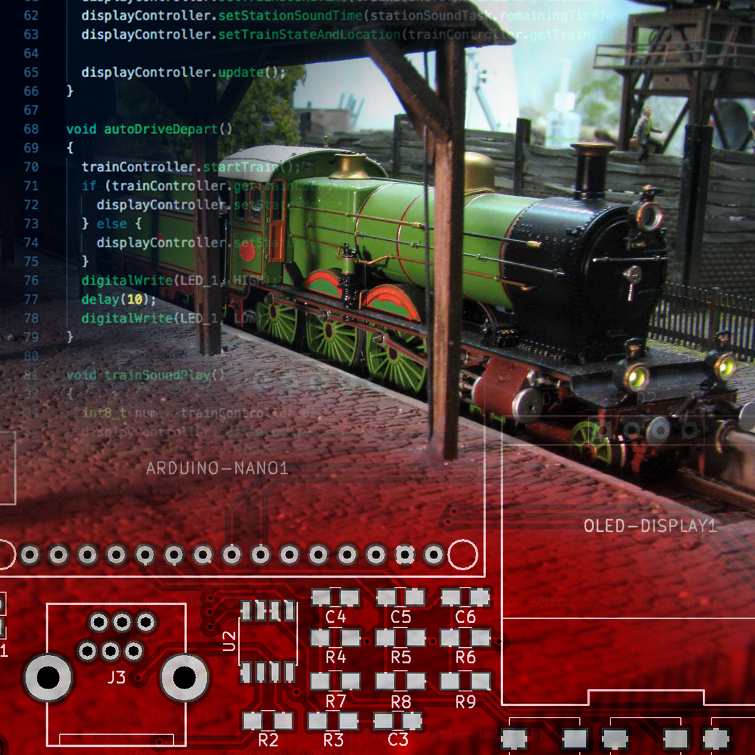
- Arduino Nano Socket
- DFPlayer Mini Socket with an external connector for a speaker.
- The MAX485 IC to allow the board to talk to the Roco MultiMAUS.
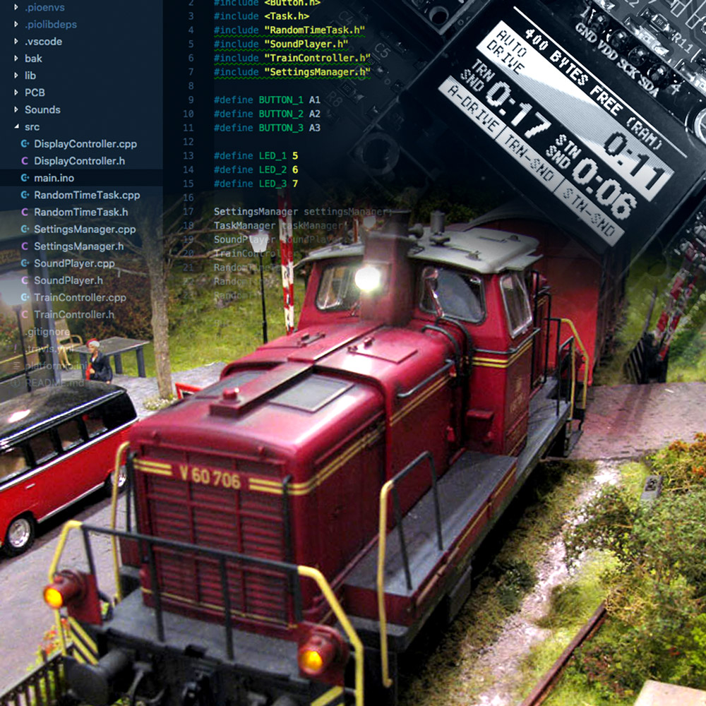
- A 0.96" I2C OLED display.
- Three SMD LED’s that can be used as visual feedback (convenient during debugging).
- Three hardware debounced push buttons.
- A RJ12 connector to connect the Roco system.
- Various JST connectors for additional GPIO ports.
- A LM7805 voltage regulator to supply power to all the components.
And with that list in mind, the next step is to draw the schematics for this project.
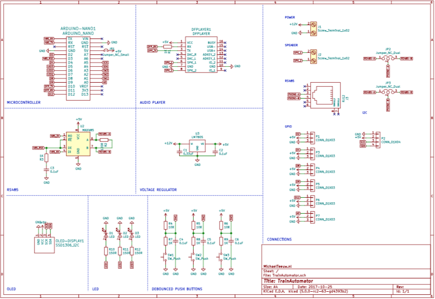
Download the PDF of the schematics here.
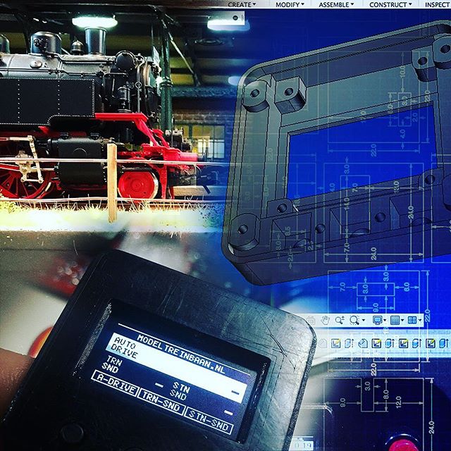
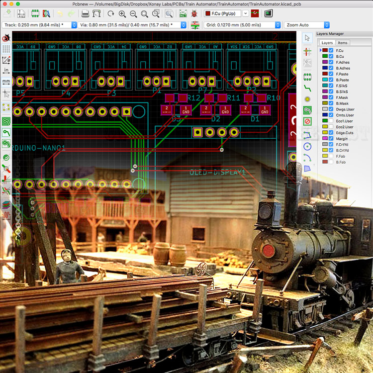
After finishing the schematics, it’s time to work on the PCB design. Granted, KiCad hs it’s quirks, but in the end you’ll be able to design some pretty sexy PCB’s.
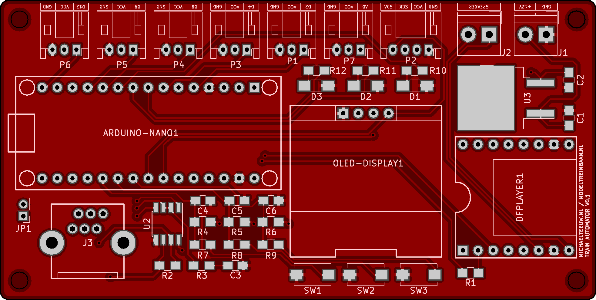
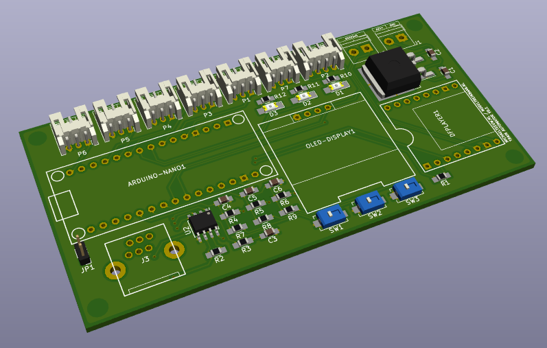
Along the way, the 3D-render function of KiCad gives you a nice feeling about the end product. I think I am on the right track here …
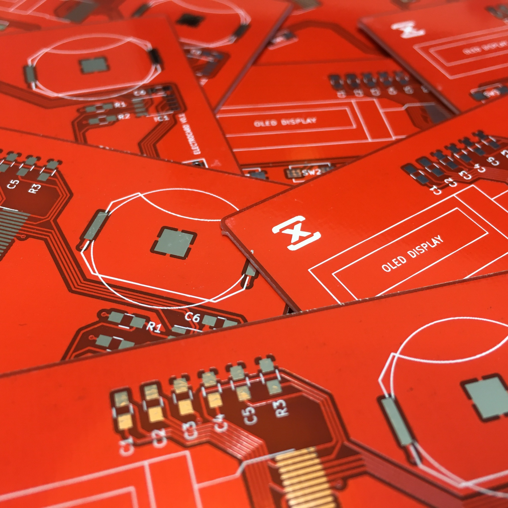
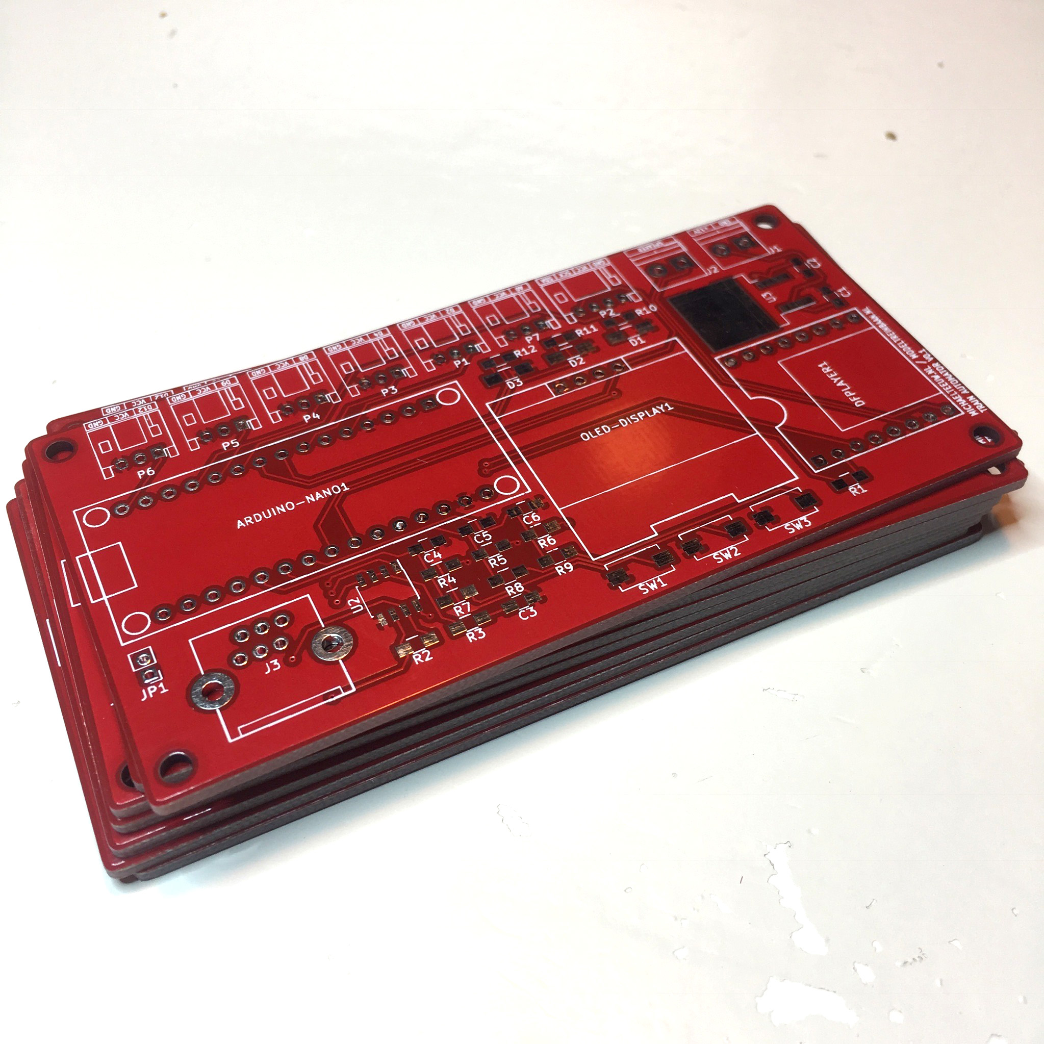
After I finished up the design, I send my order to one of the Chinese manufacturers, and within a few days this stack of beauties arrived on my doorstep.
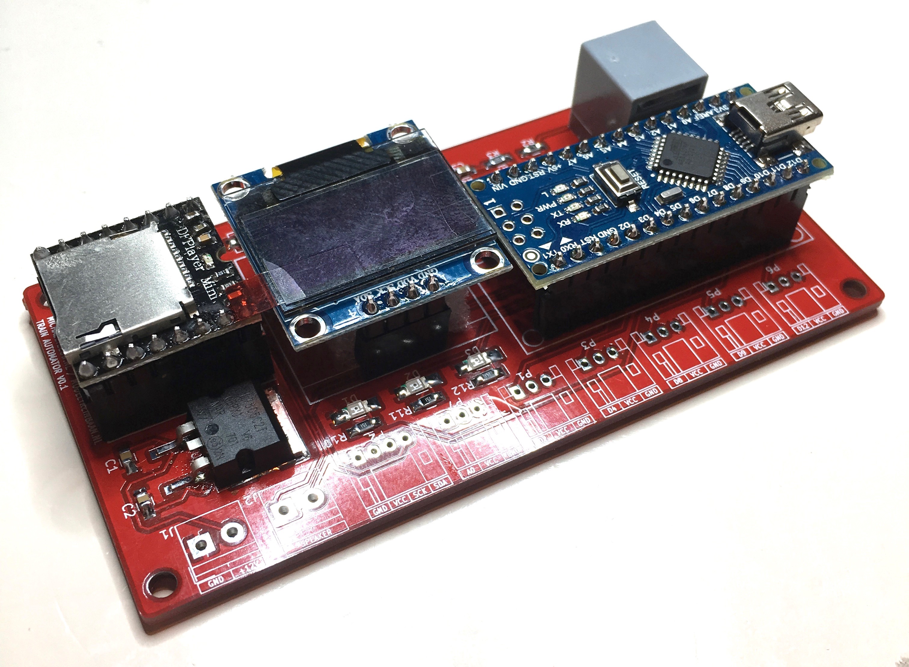
Some solder, some heat and a few bottles of midnight oil later, the first populated board turned out better than expected. I must day I’m really a fan of SMD soldering.
If I would make a second version of this board, I’d integrate the ATMega328 and remove the need for the header pins between the display and the DFPlayer. You know, just to make it look even nicer.
Of course I did goof up at some points:
- I used the wrong footprint for the JST connectors. I own boxes of 2.54mm spaced JST connectors, but used the 2mm footprint. Not a big deal: we just solder the wires directly to the board (or order some 2mm connectors if needed).
- I added a jumper to disconnect the Arduino from the board’s power to allow me to connect it to my computer while it’s on the board. Unfortunately I forgot to add a jumper of switch to disconnect the serial lines from the MAX485 IC. This prevents me from programming the Arduino while it’s on the board.
- I added hardware debounced buttons to the board, but those buttons need to be connected to external buttons. It would be much nicer if I added a connector for this as well. Right now I need to solder some wires to the button pads.

Luckily, none of those points are show stoppers. But if I ever need to order a second batch of this board. It might be worthwhile to make the nessecery modifications.
Want to build this controller yourself? Download the Gerber files here. Or get the full KiCad project here. Keep in mind that it comes wihtout ANY form of support. :)
Train Automator: Writing the Software