If you you are a tinkerer that likes to play around with Arduino’s and electronics, you’ve probably played around with a 4 pin I2C OLED display more than once. To step up my game, I thought it would be fun to give myself a little challenge and try out a barebone OLED screen without the convenient breakout board.
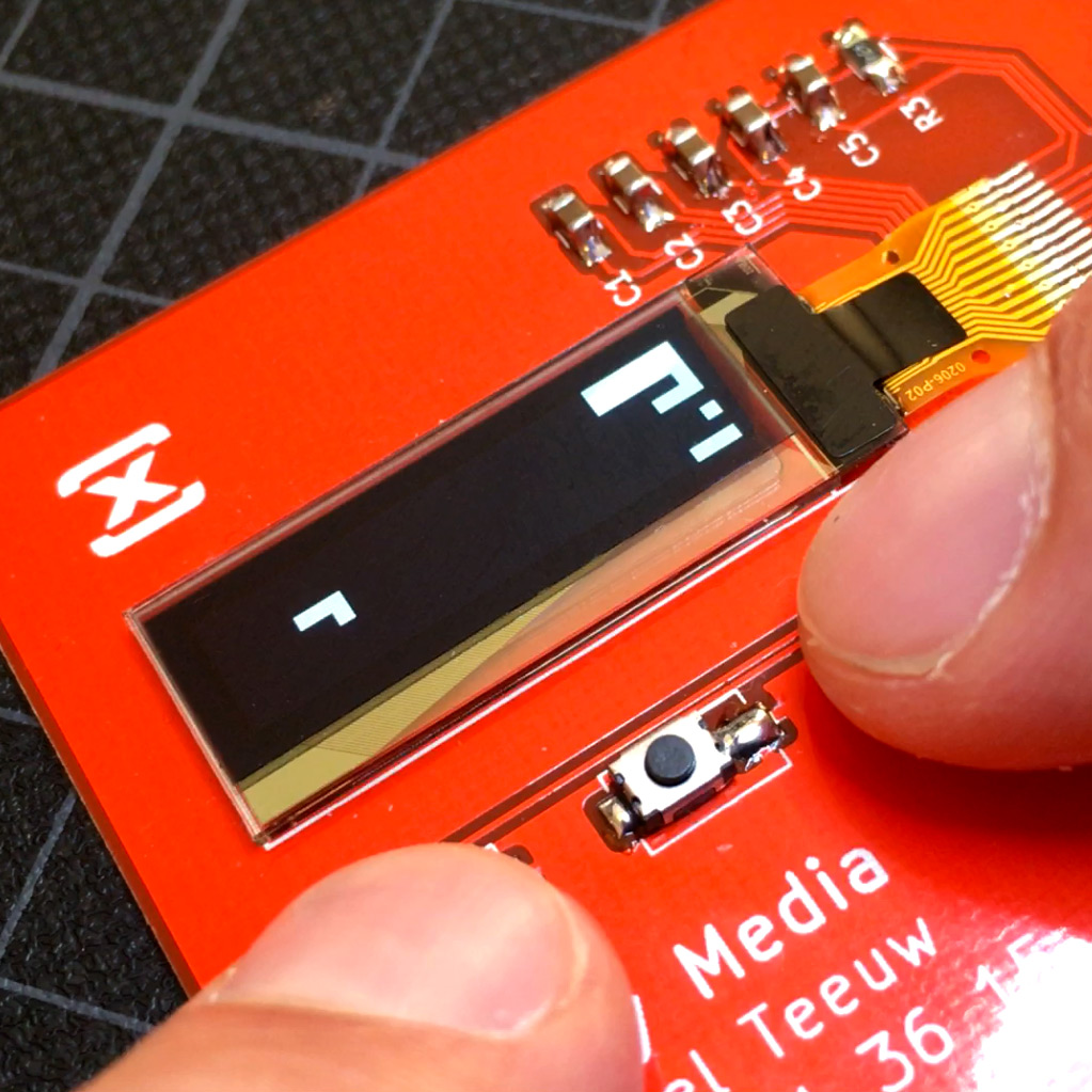
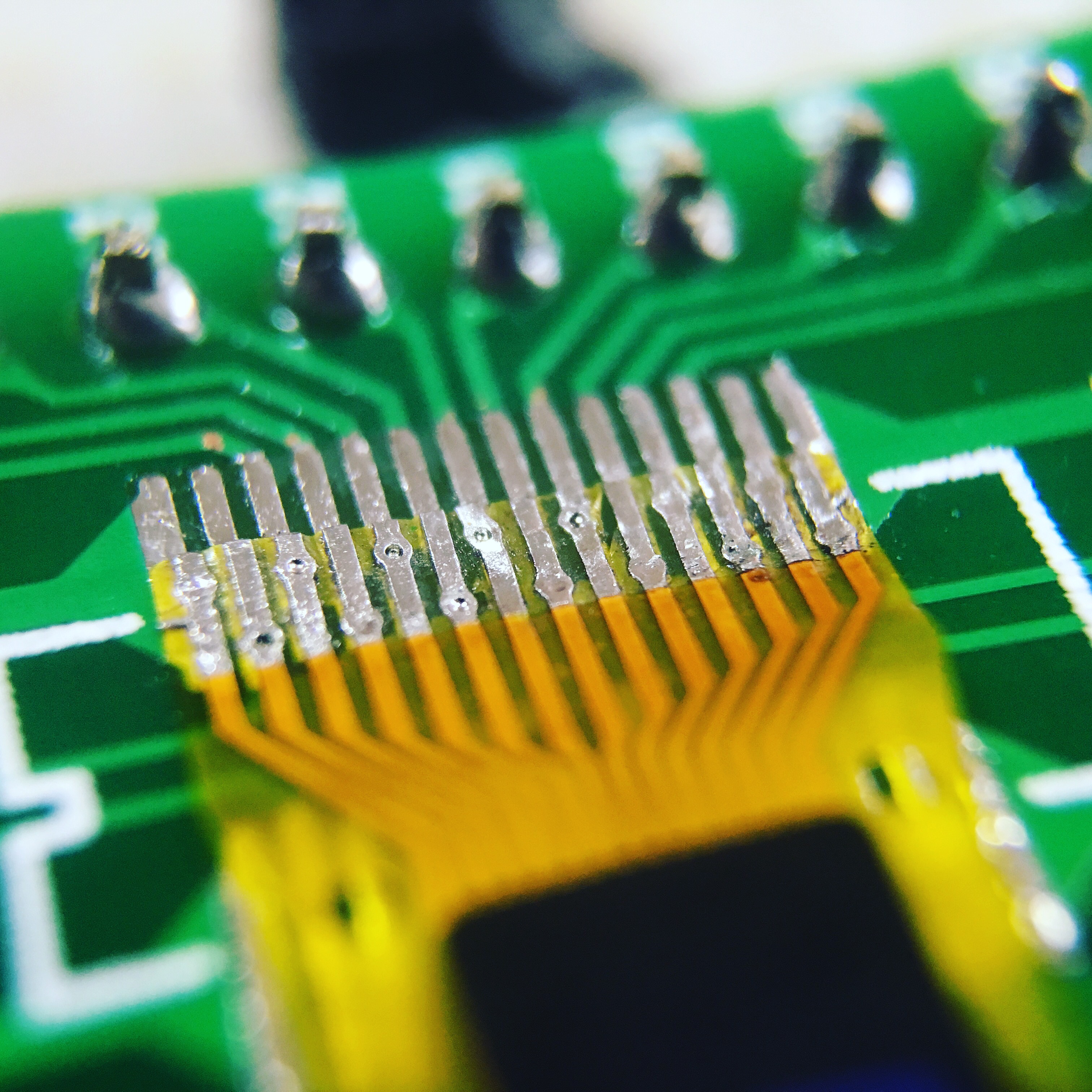
Because I have a nice project in mind which could use a small OLED screen, I ordered two 96x16 pixel, 0.69" OLED displays with a 14 pin connector. Wow, those are small! Just like the 4 pin break out board versions, they feature a SSD1306 controller inside, allowing them to be controlled over I2C.
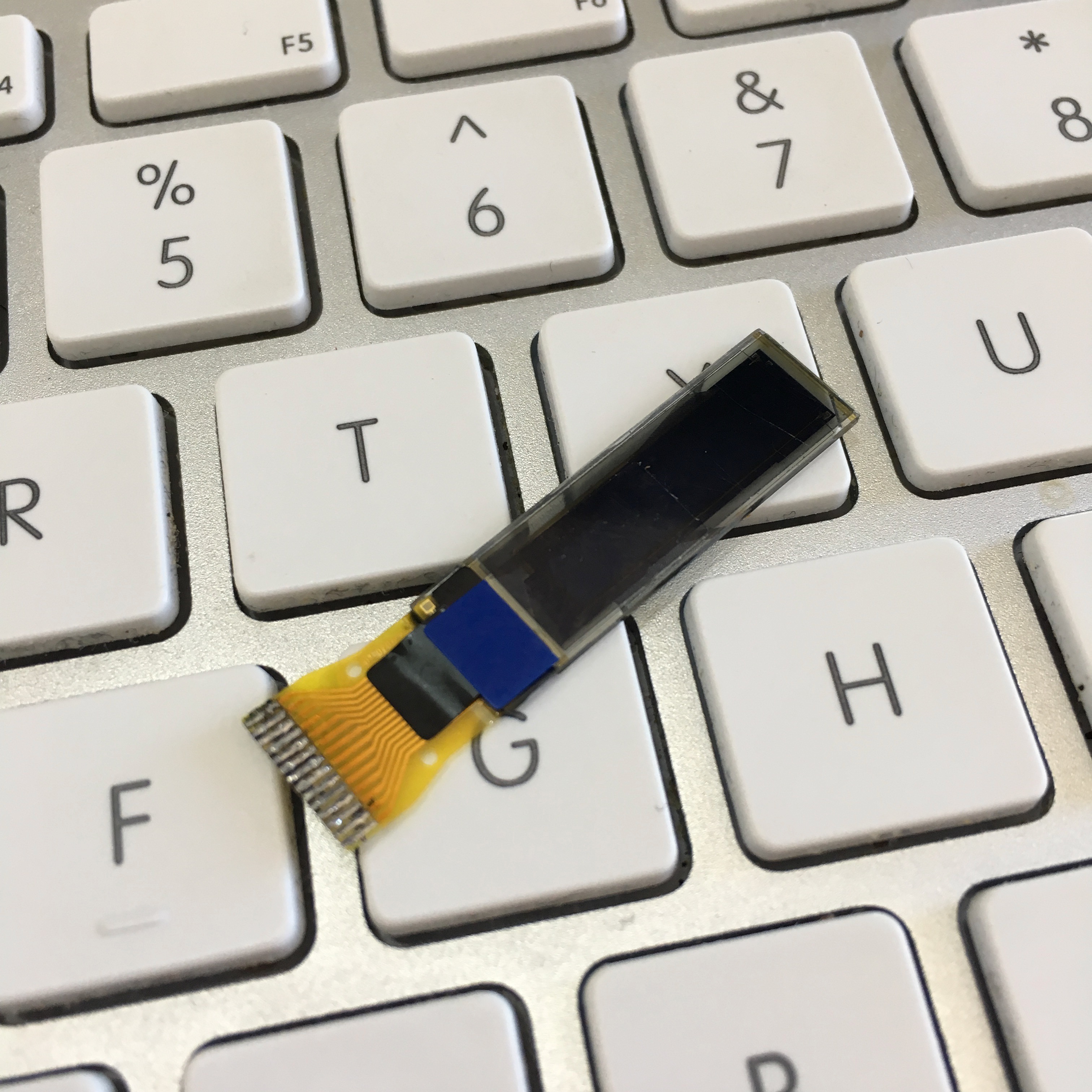
As you might notice on the photo above, the connector is already tinned and has a lot of ugly black residue on it. This is because of my first failed attempt to start using them …
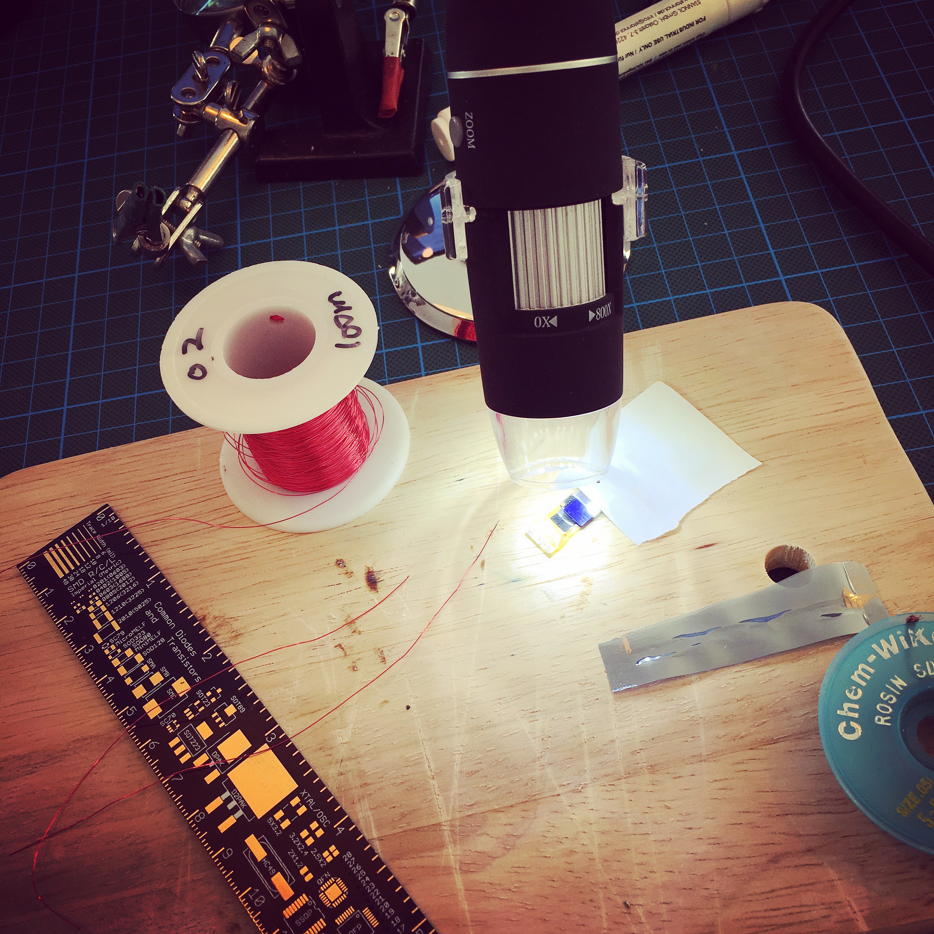
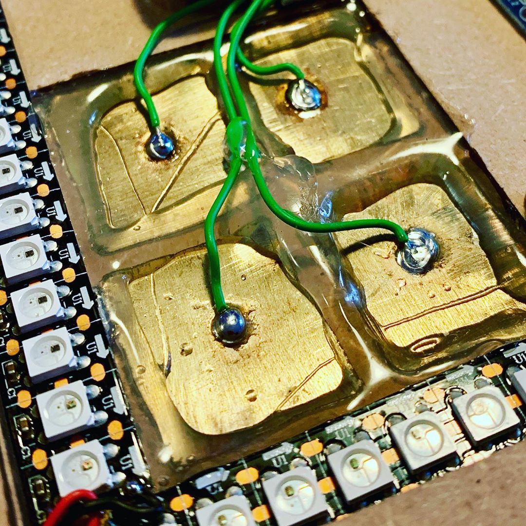
I initially thought it would be a good idea to solder some 0.2mm wire to the 0.32mm smd pads. But boy, did I underestimate how difficult that would be! Even with the help of a (cheap USB) microscope!
Time to scratch that attempt and take an easier approach. I ordered a few SMD breakout boards that allowed me to use simple header pins on a breadboard and solder the OLED screen onto the SMD pads.
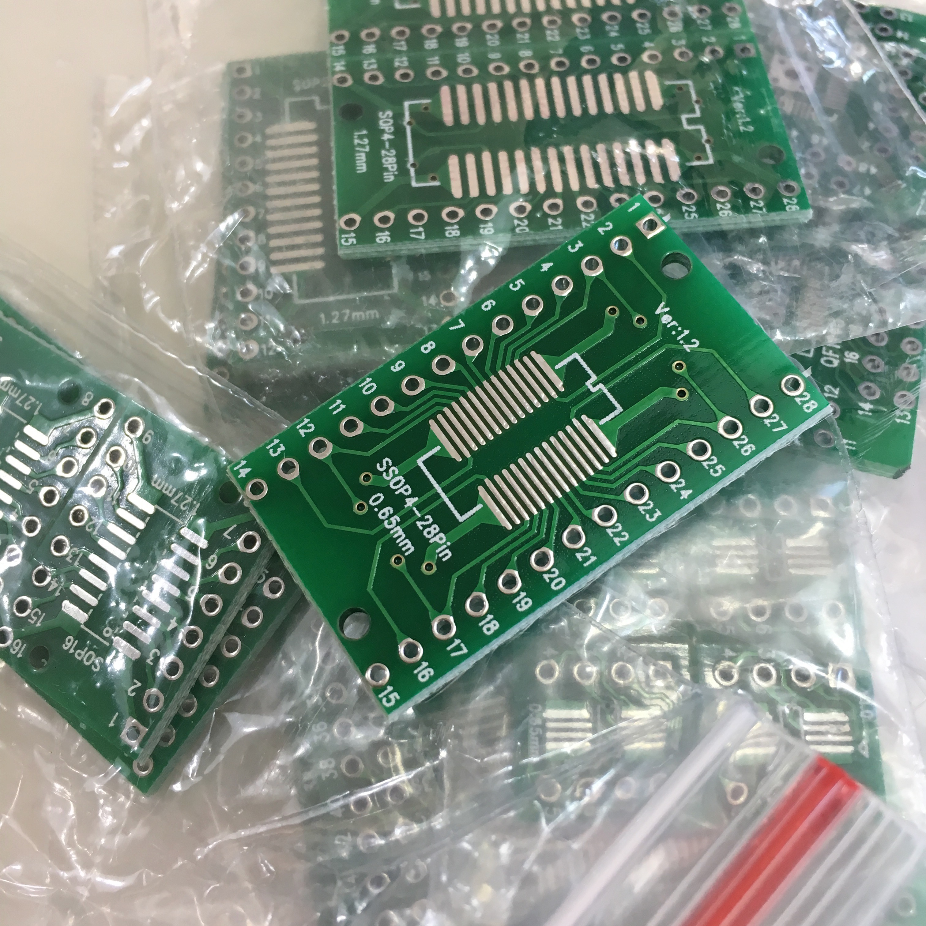
Even this was a bit of a challenge, since the breakout board uses 0.65mm spacing, while the OLED screen uses 0.62mm spacing. But with a lot of patience, a steady hand some cussing and a few prayers, I managed to get it working.
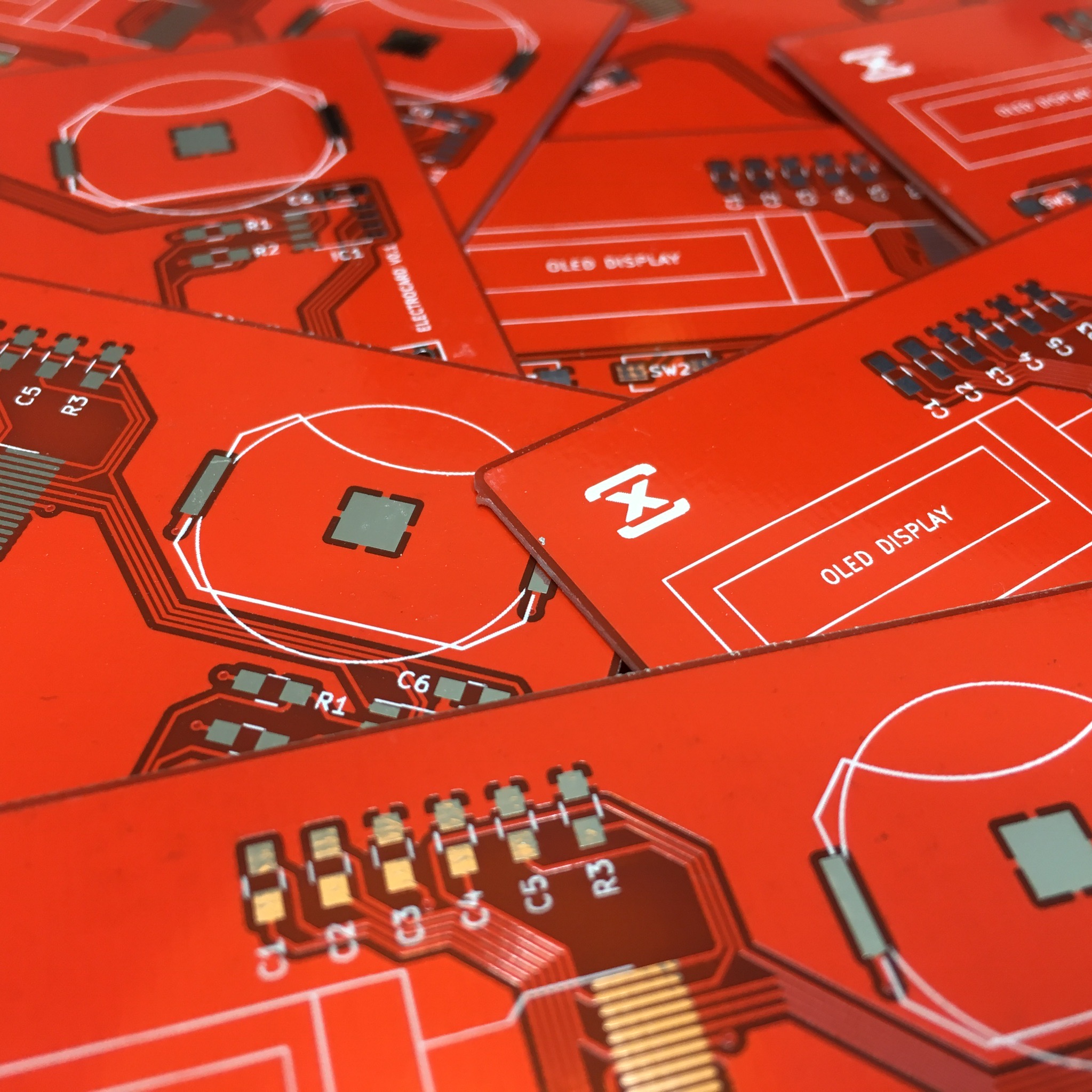
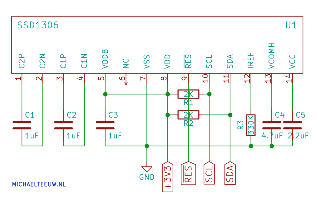
The next step is to setup the schematics. The OLED needs a bunch of capacitors and resistors to do it’s job. So to figure out how to connect it, I studied the datasheet.
Now, I can pretend I completely understood all of the info in the datasheet, or I can just confess I reached out to Jan Adriaensen, who has a lot of YouTube video’s where he shows his OLED magic.
Jan cleared up some of my confusion, which allowed me to understand the schematics of the datasheet. Thanks Jan! To make it a bit simpler, I used KiCad to work out his suggestions which resulted in the following schematics:
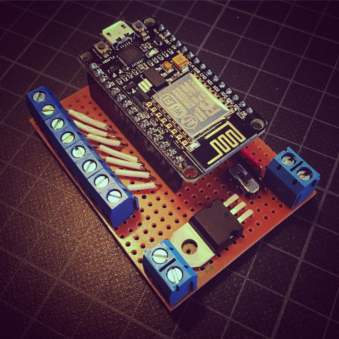
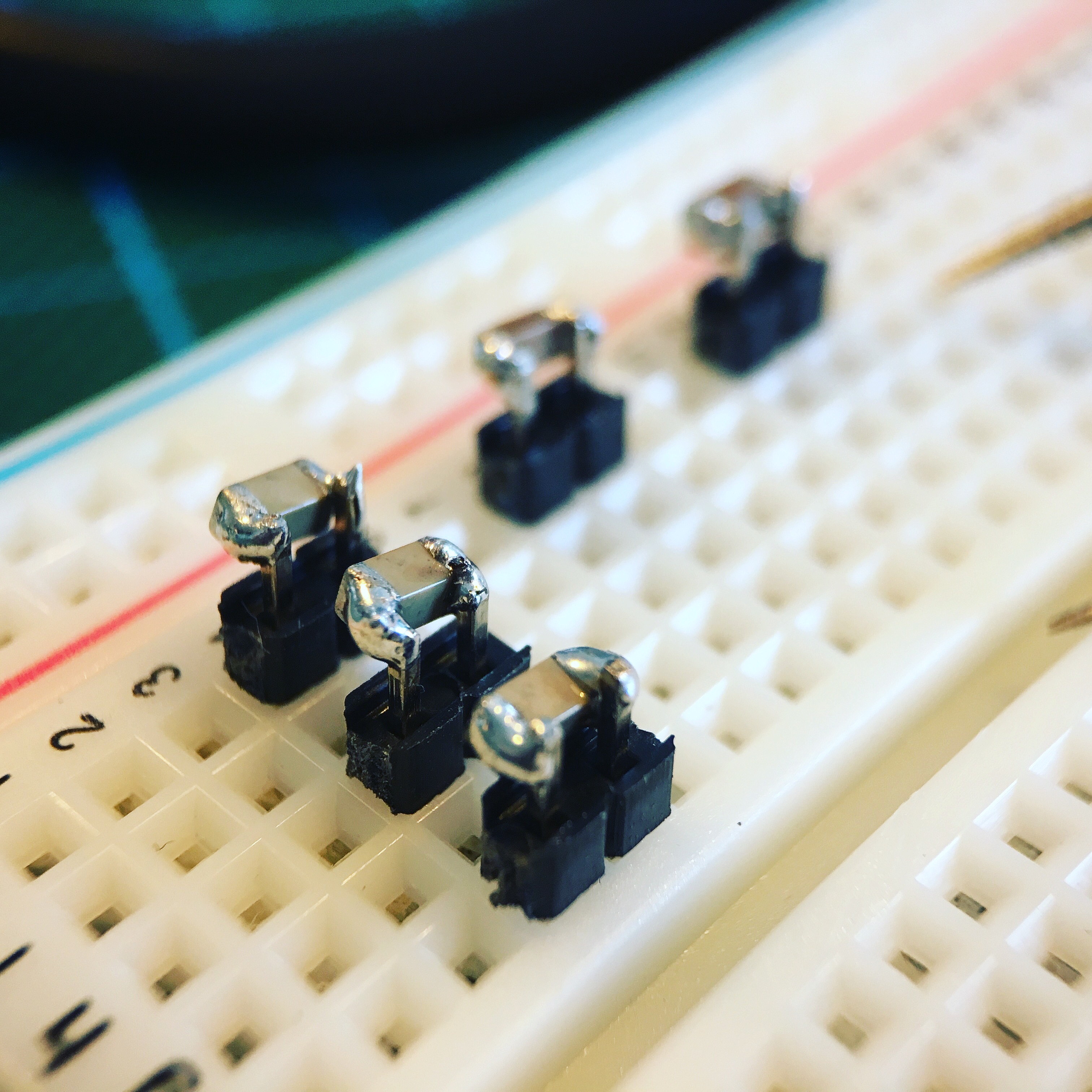
The next step was to set everything up on a breadboard. Unfortunately I didn’t have most of the through hole caps needed for this project, so I had to be a bit creative with a bunch of SMD caps and some header pins.
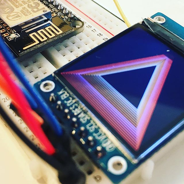
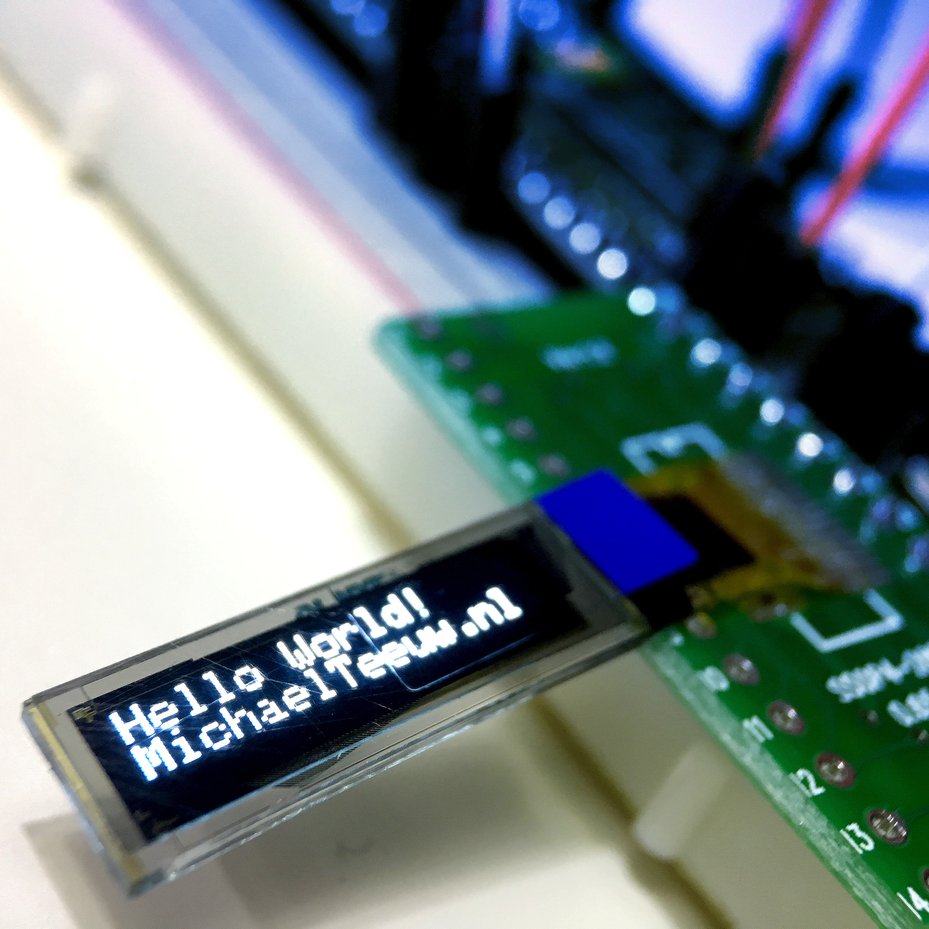
And with that last obstacle out of the way, I could put everything in place. Now, since the OLED is a 3v3 device, and I didn’t set up any level shifting, I needed a 3v3 MCU. Because of this I used an ESP8266 for testing. Of course, a 3v3 Arduino would work evenly well.
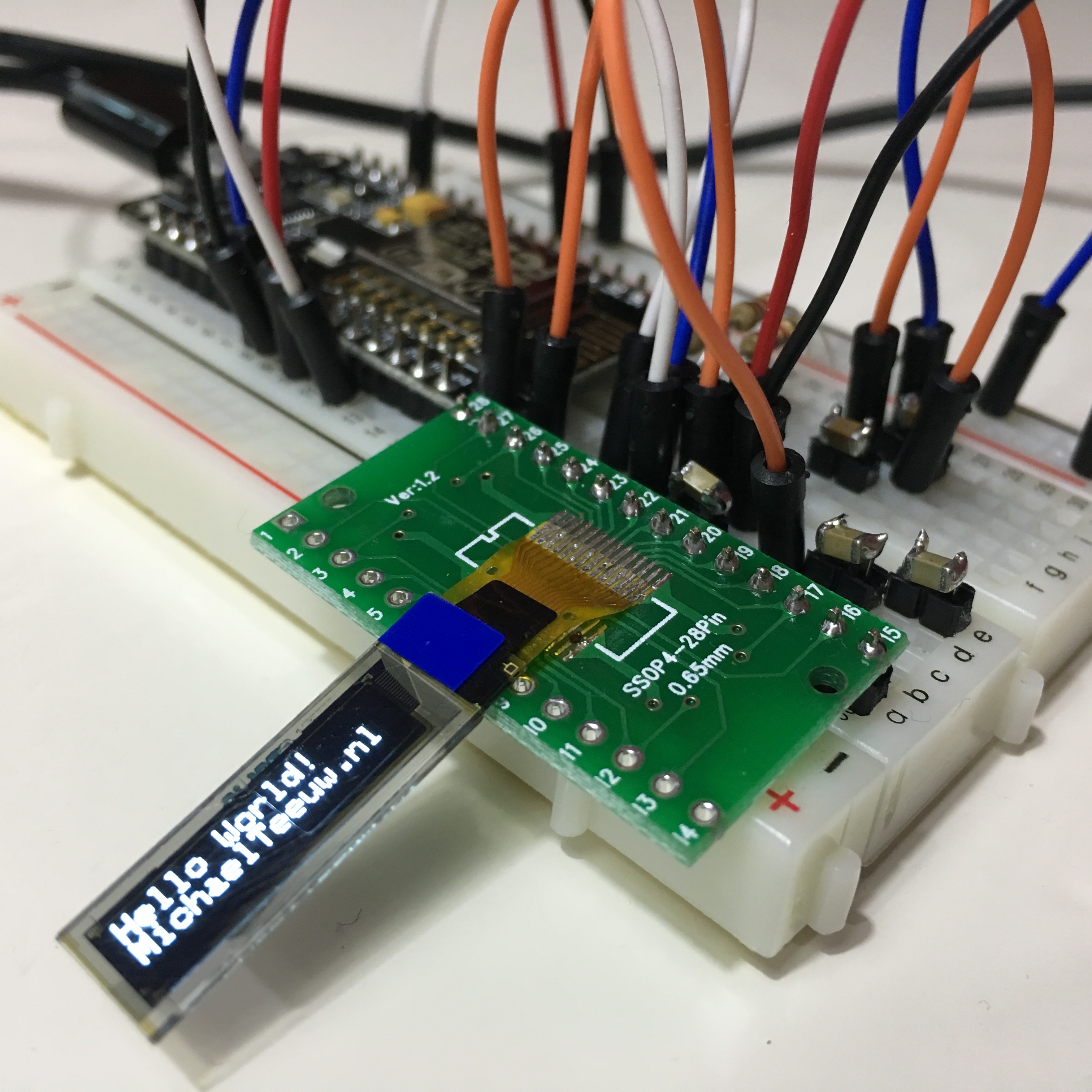
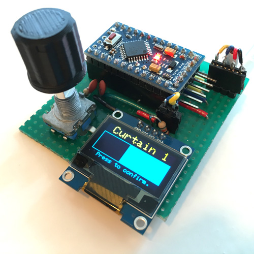
To test the display, I used Adafruit’s SSD1306 library, which conveniently supports the ESP8266 and these small 96x16 displays. As well as the 128x32 and 128x64 the ones. And as you can see, it worked like a charm!
Mission accomplished!

Speaking of those other small displays: I ordered a few of the 128x32 barebone OLED’s (the 128x64 hasn’t got the same 14 pin connection) for that future project. If you’re curious, make sure to keep an eye on my blog …