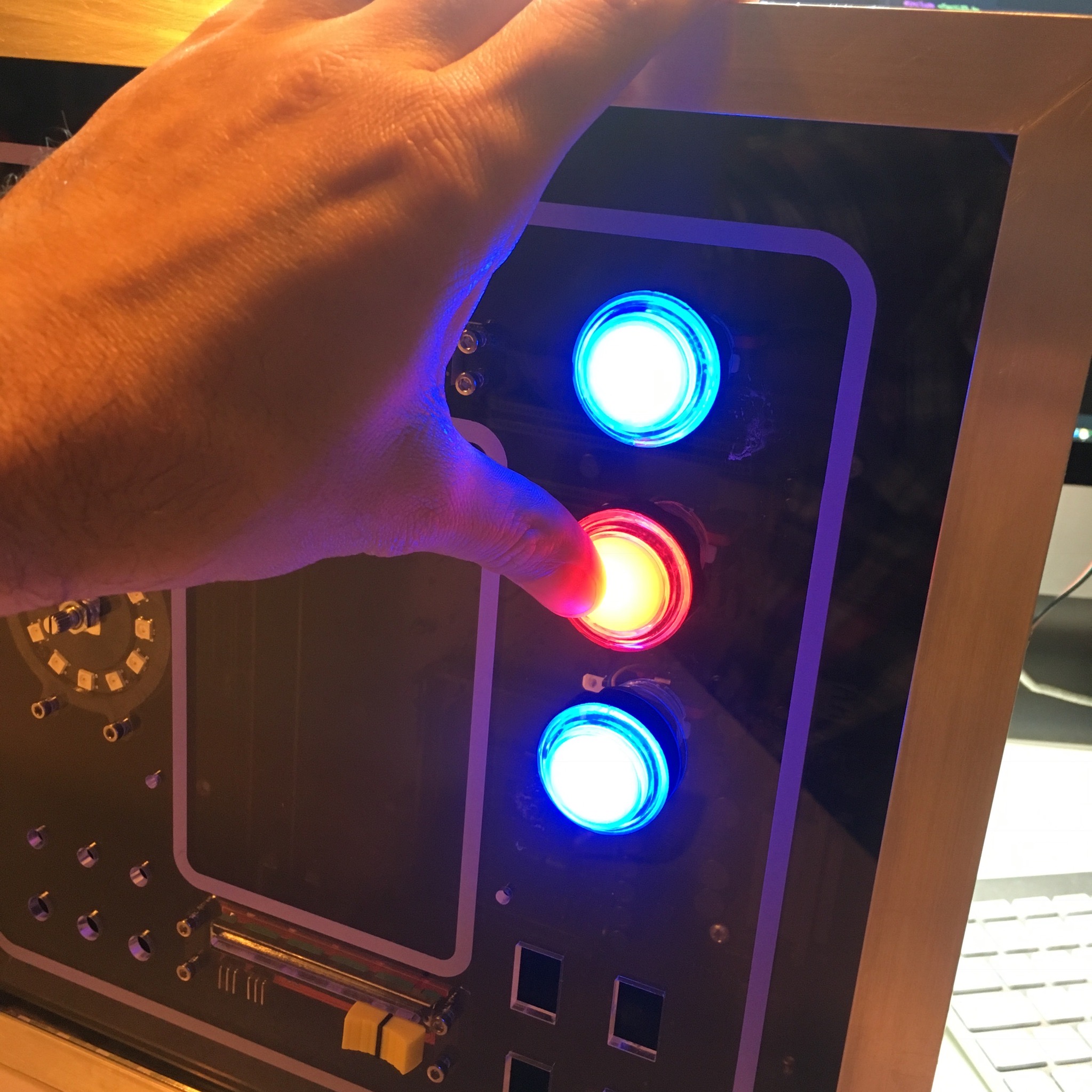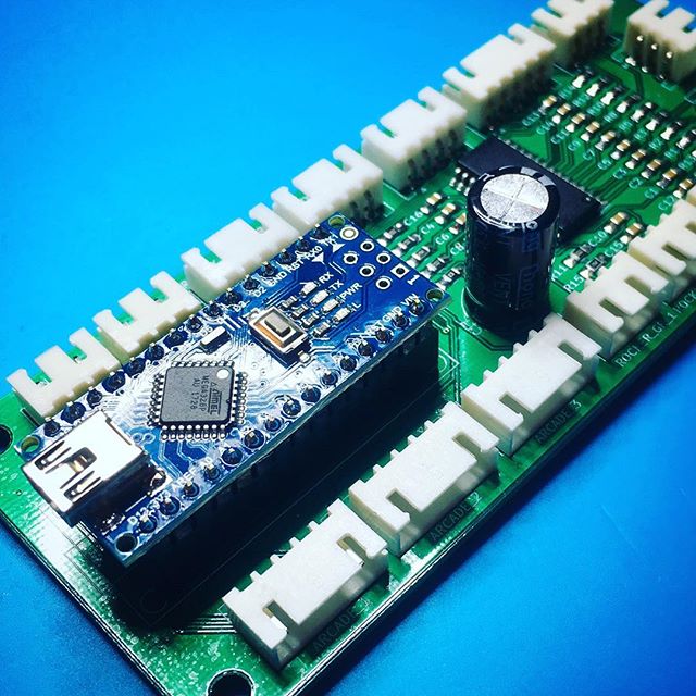
After a succesful intergration of the push buttons it is time to wrap up the front panel. With 9 switches, 3 buttons, 2 displays, 1 slide pot, 1 rotary encoder and a lot of LEDs, this includes a lot of wiring.
Activity Board: Push the button!
To start of easy, I’ll print some spacers to mount the slide pot to the acrylic front panel.
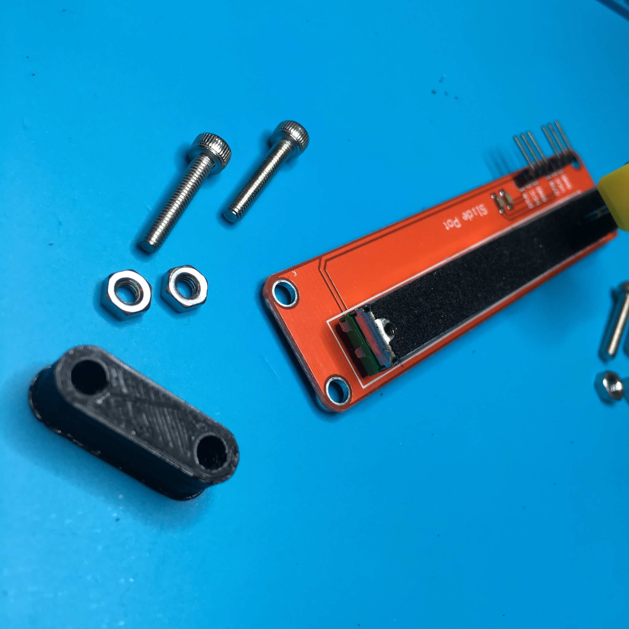
A minor adjustment in size allows me to use similar spacers for the 7 segment display.

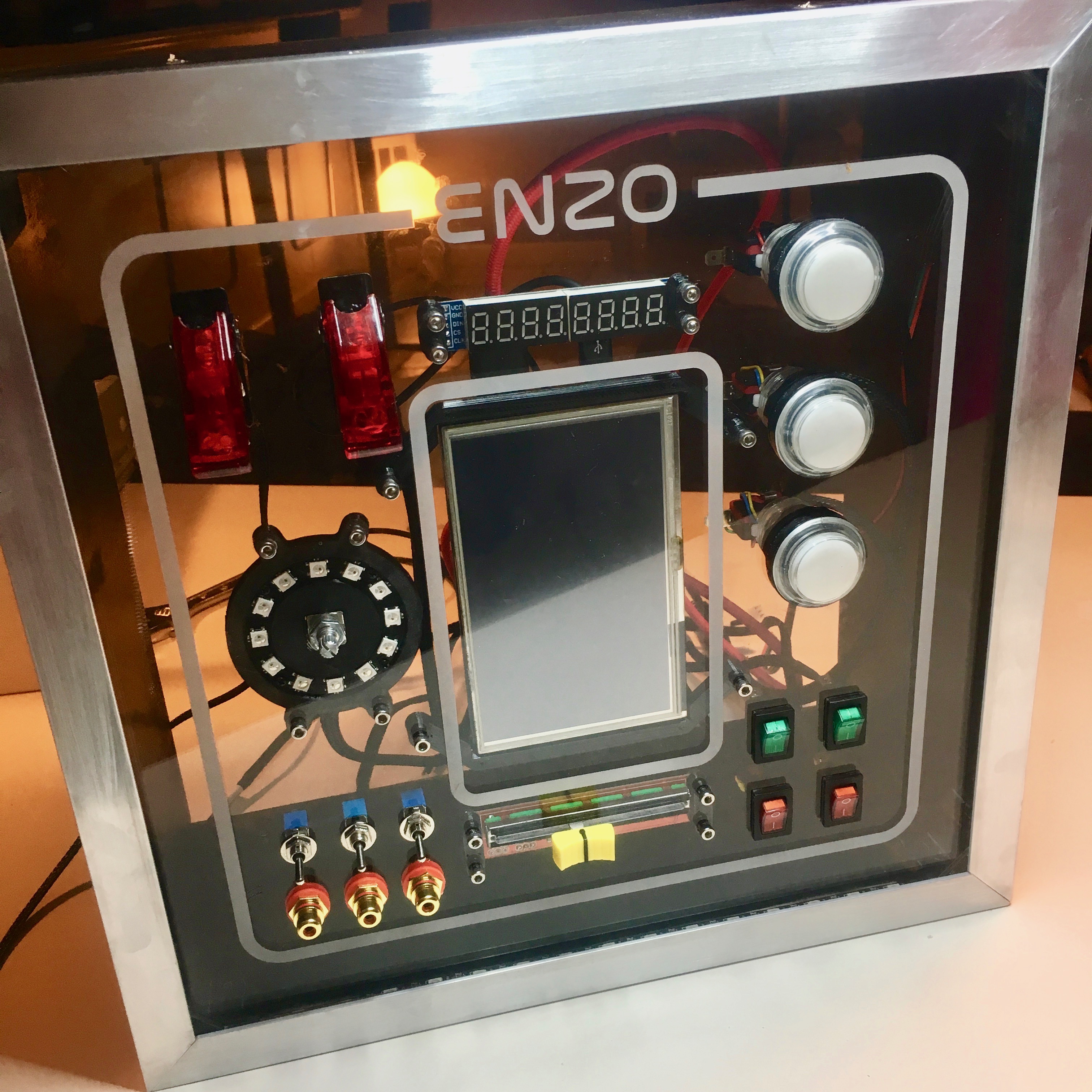
The small HDMI screen also needs some mounting brackets. Since I designed the front panel layout myself, the dimensions were very easy to sketch up.

The rotary encoder uses the the most sophisticated mount. It has a special cutout for the Neopixel ring. 4 tiny screws keep the ring in place. In the back it has all the necessary holes to connect the wires to the ring.

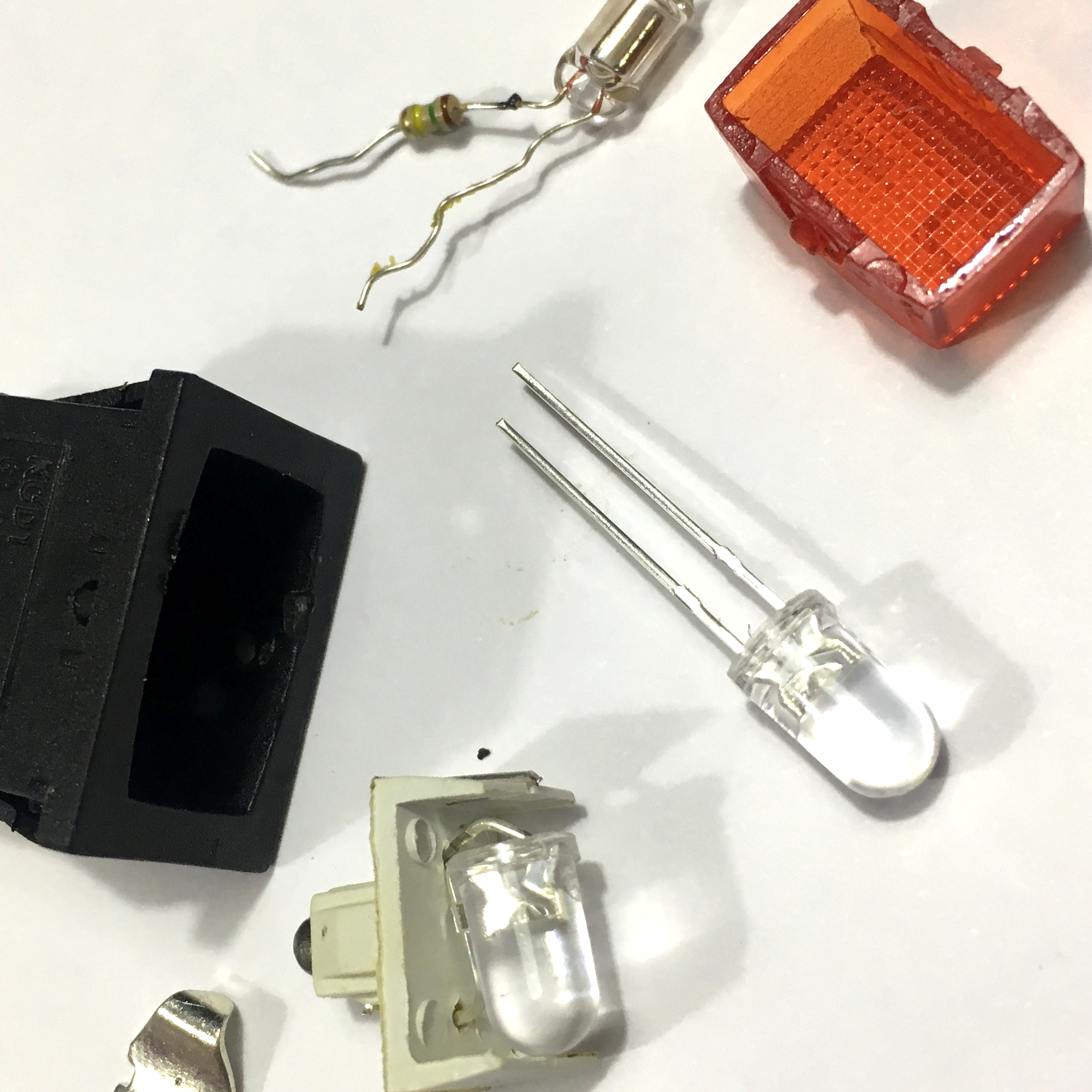
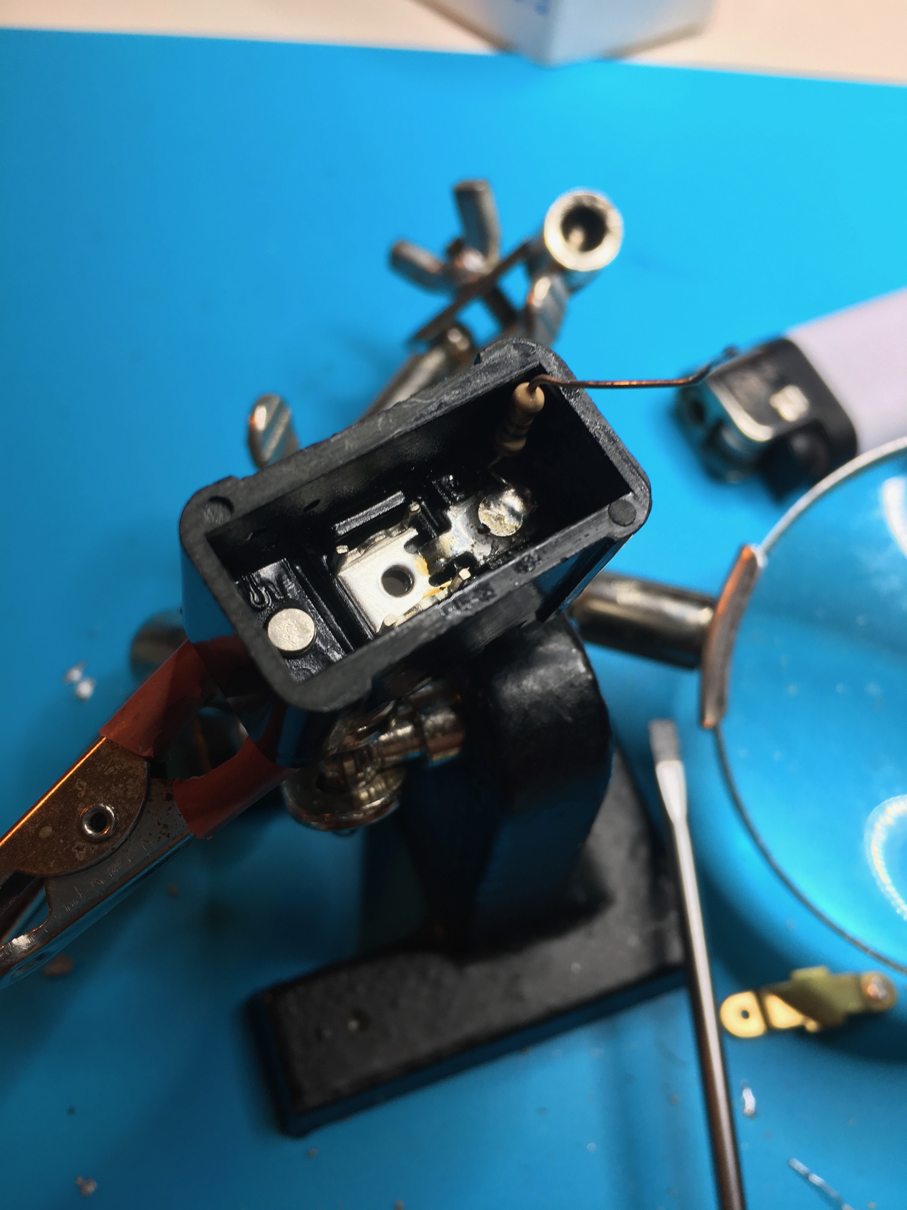
The two main flip switches need a little extra attention. It turns out the switches use a common anode for the switch and led. Since I want to pull an Arduino input to ground when flipping the switch, I need to reverse the LED’s wiring.
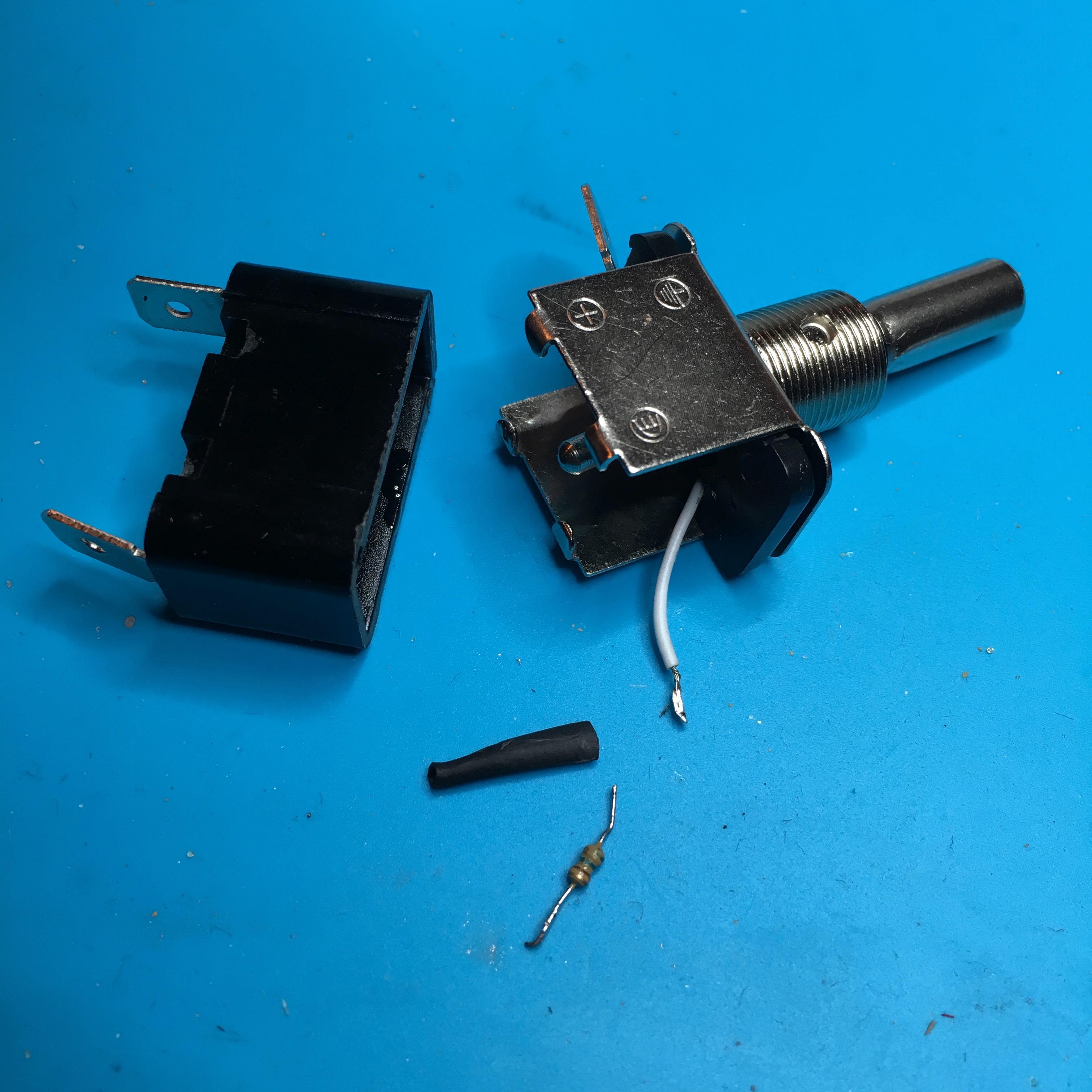
And while it was working on, I swapped out the resisor for a 150 ohm version. It originally had 560 ohm resistor to work on 12V. The 150 ohm will allow me to control the led with 5V from the Arduino.
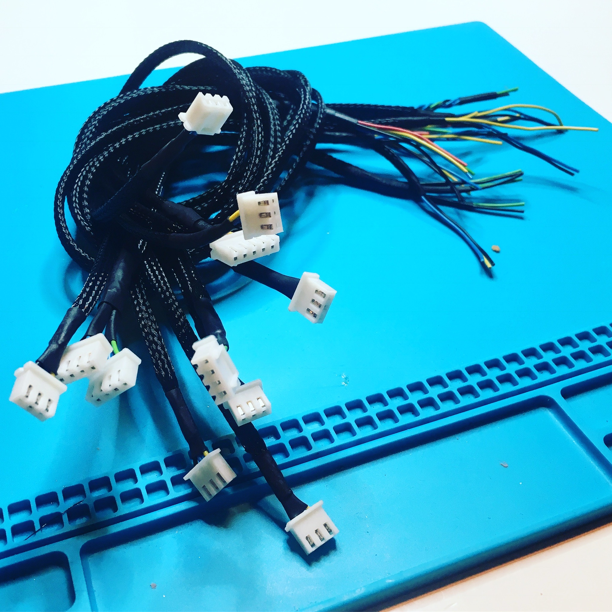
A cosy winter night, meters of wire, a lot of braided wire harnessing, a few pieces of heat shrink and a bunch of JST-connectors result in a a professionally looking bundle of cables.
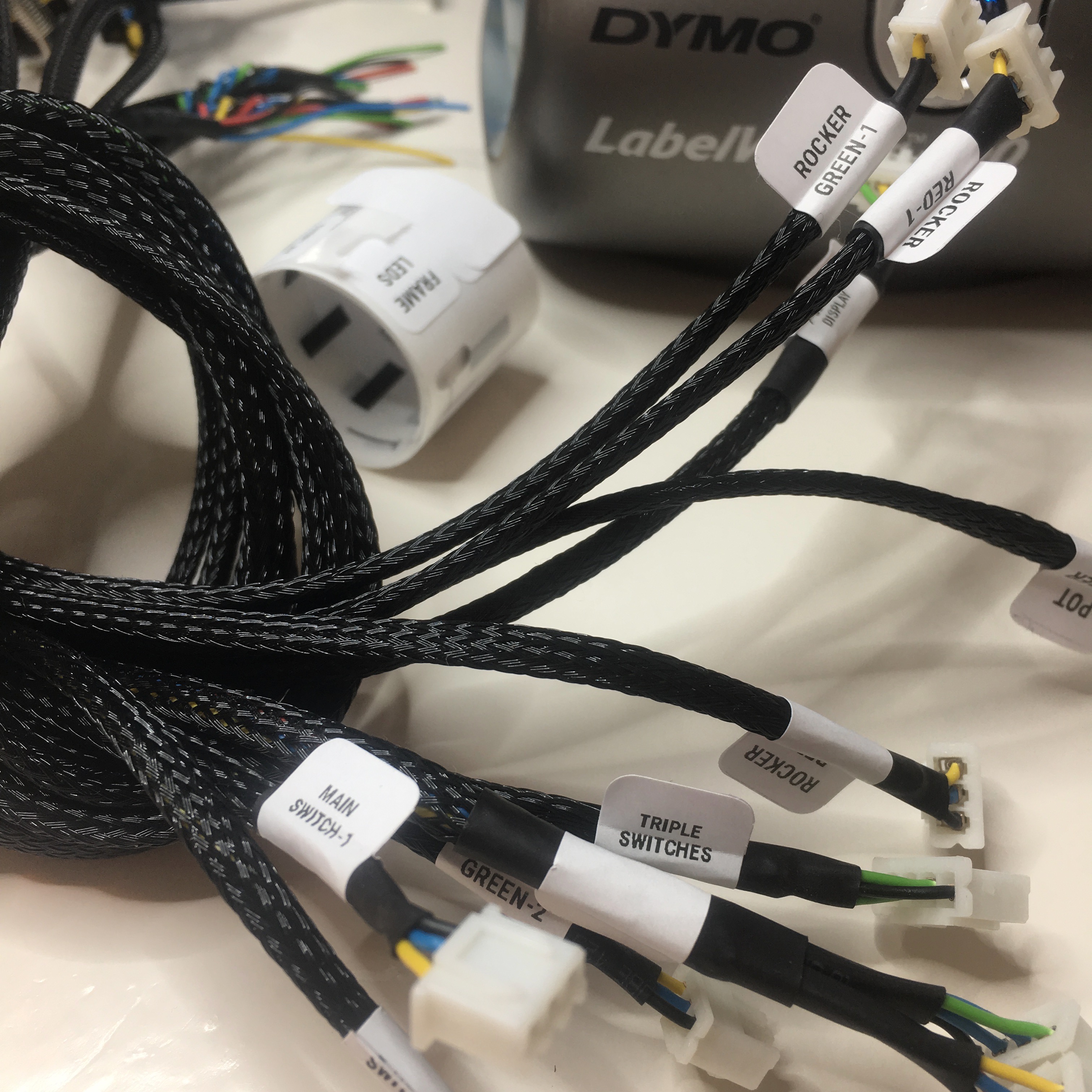
To prevent future-me from mixing of the cables, I use a Dymo label writer to print small labels for all the cables. I’m sure future-me will thank me for this later.
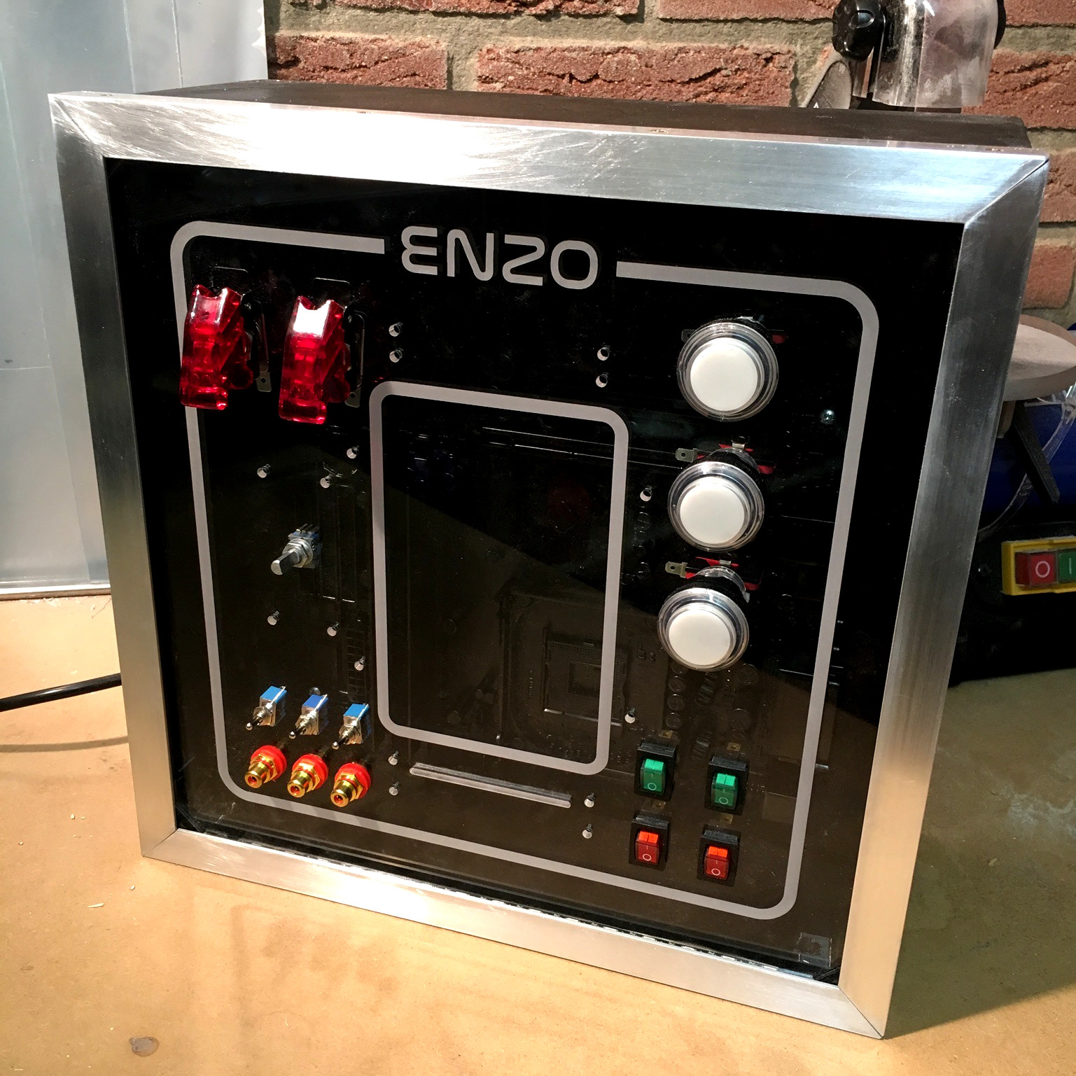
After soldering all the cables to the buttons, switches, and displays it’s finally time to assemble the panel and put everything in place.
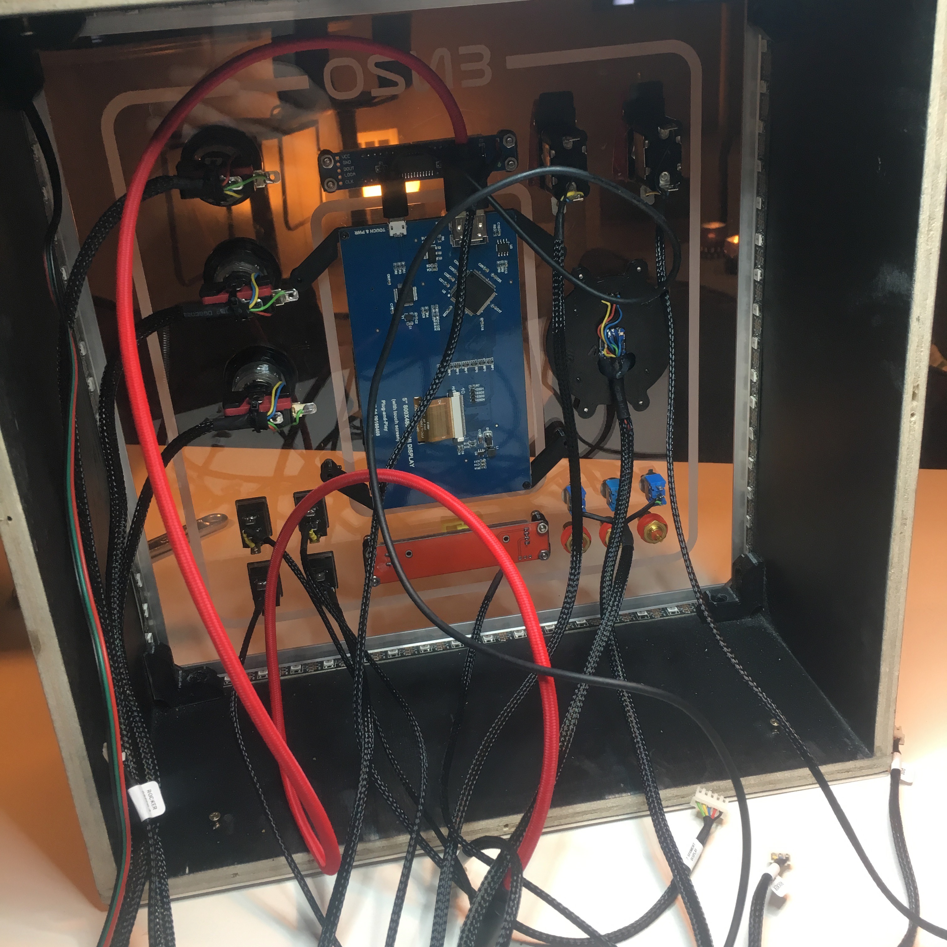
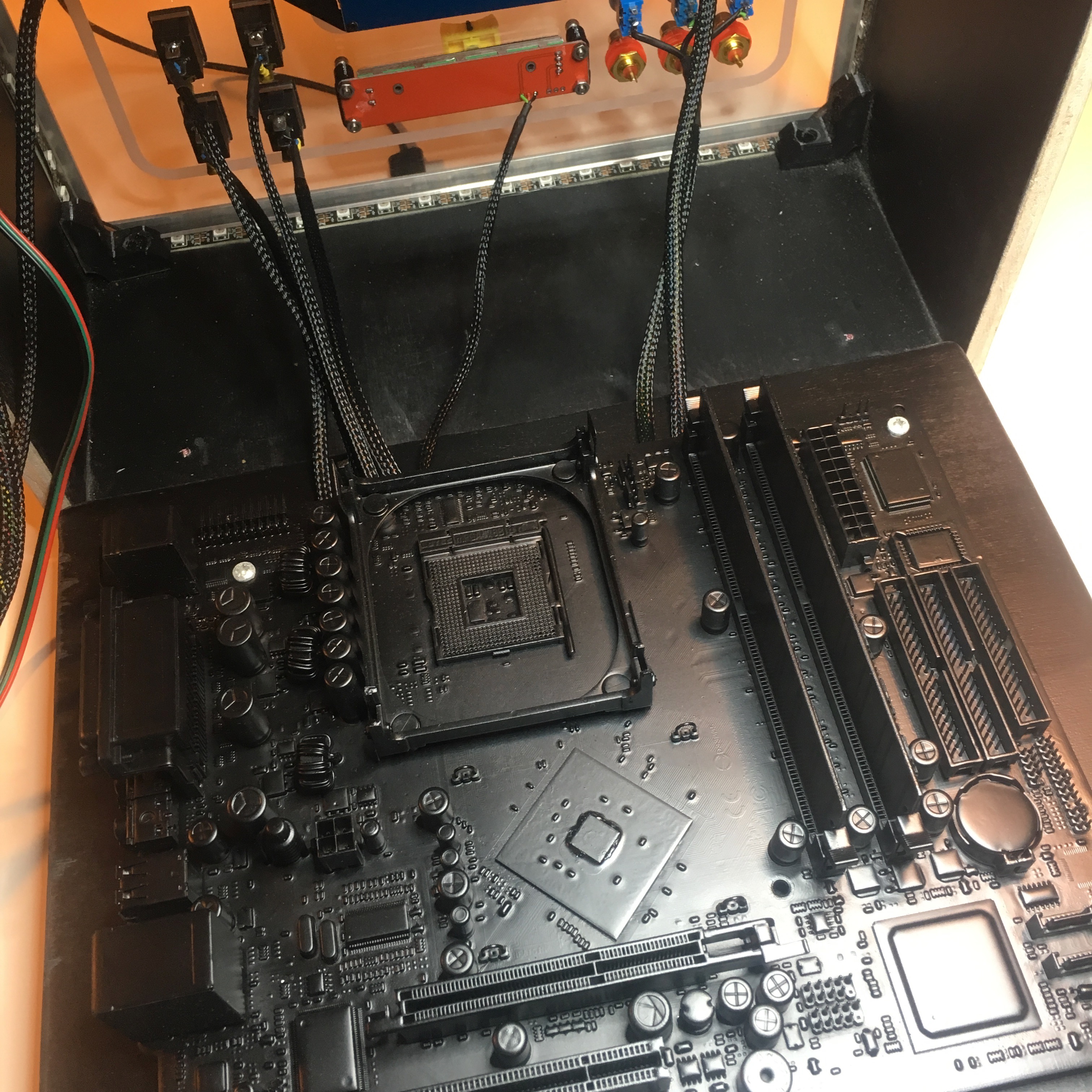
All the cables will be routed behind the spray painted motherboard.
And with everything in place, you can really see the difference the braided cables make. The red cable is the HDMI cable for the screen. I only had a red cable laying around, but I must say this somehow gives the it a nice touch. It looks like the system’s main artery.
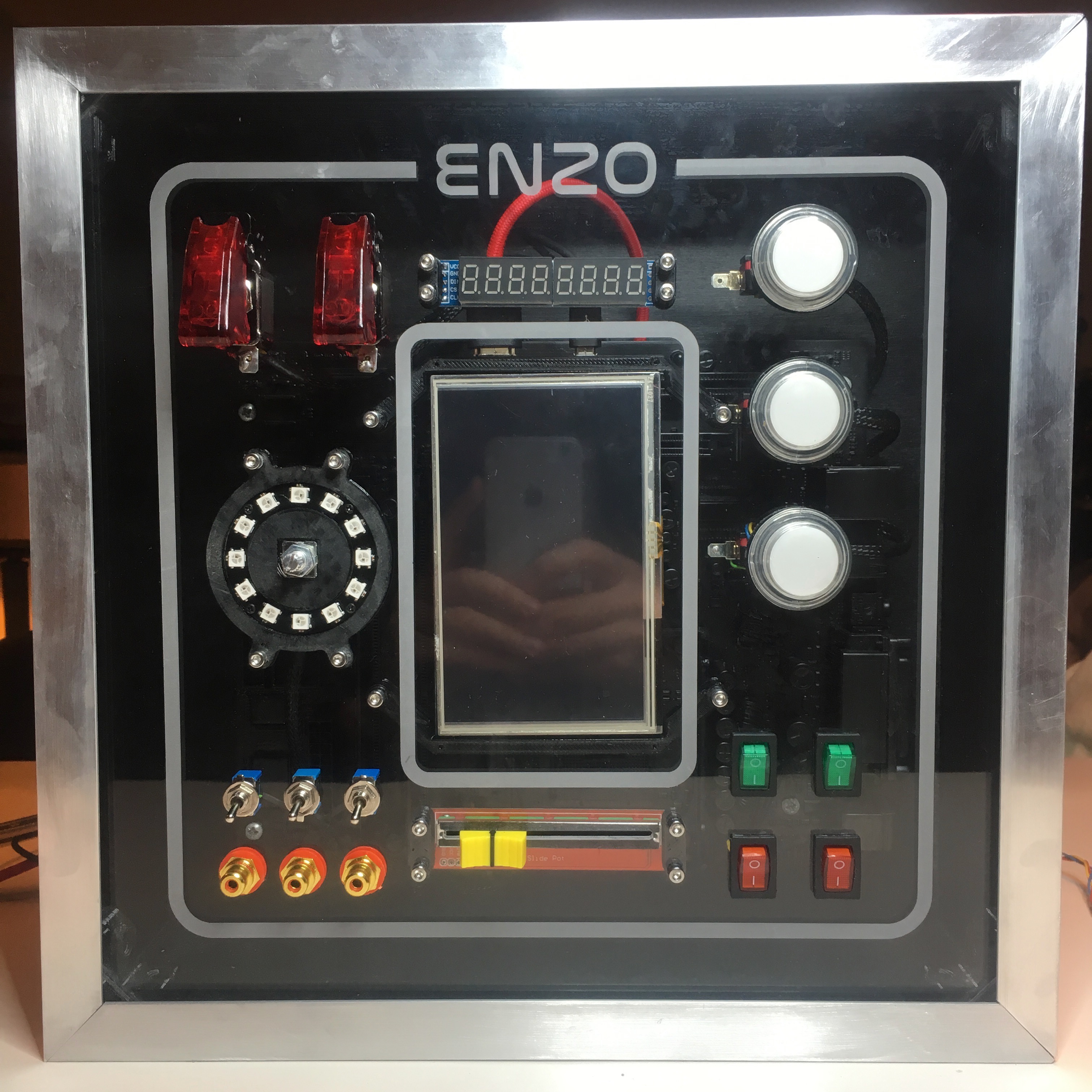
Of course, the rotary encoder needs a big round 3d-printed knob, but this is something I’ll take care of in a future post.
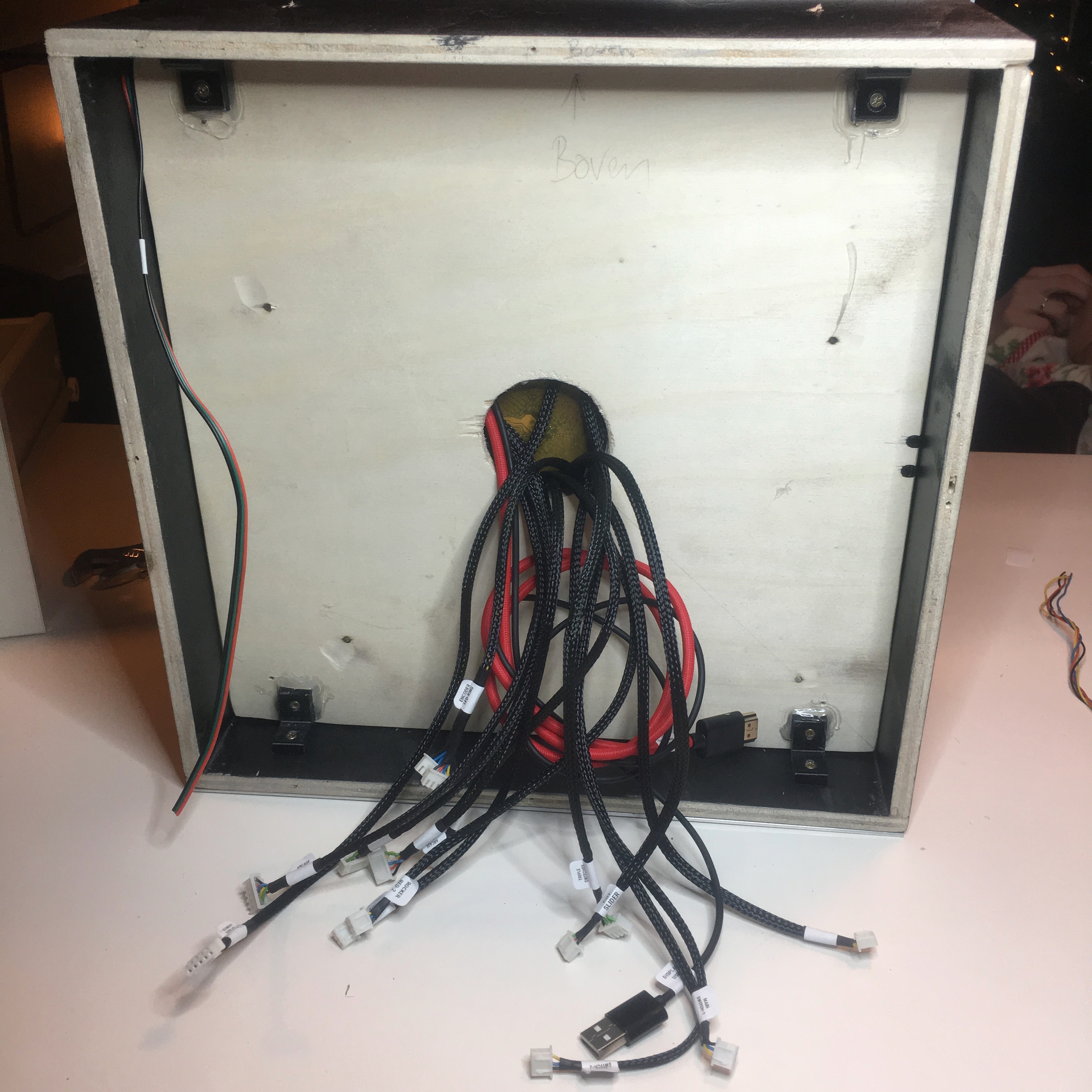
The backside shows the impressive amount of cables I need to connect to an Arduino. I’m sure as hell am happy I labeled all the cables. Thanks past-me. Nice work!

Activity Board: The dial on the board goes round and round