In my last activity board blog post I finished the final part of the control panel. It is time to start working on the electronics. Or to use a bit more exciting terminology: it is time to work on the activity board controller!
Activity Board: The dial on the board goes round and round
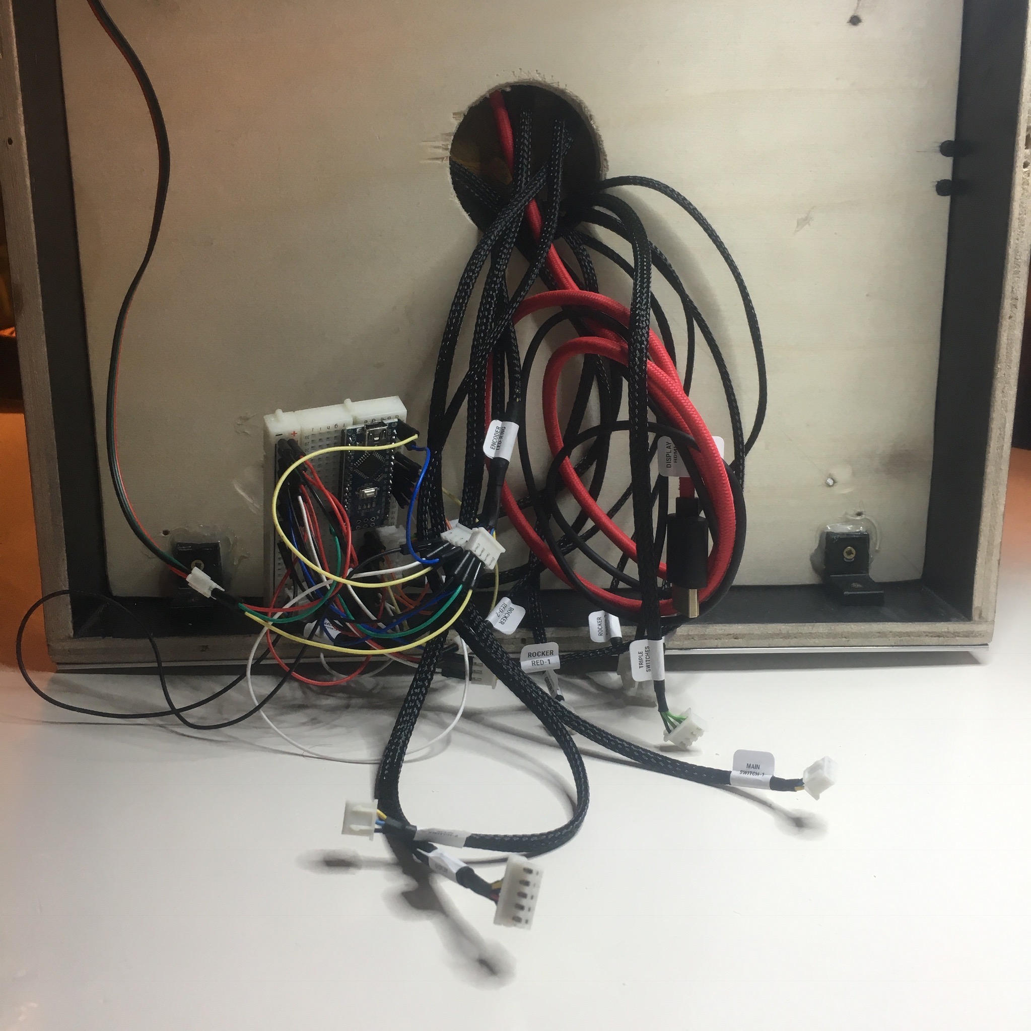
Enzo did enjoy playing with the current test setup. But a breadboard with an explosion of unorganized wires probably wont last forever. Not to mention most of the items aren’t connected yet. Time to work on a more professional and permanent solution.

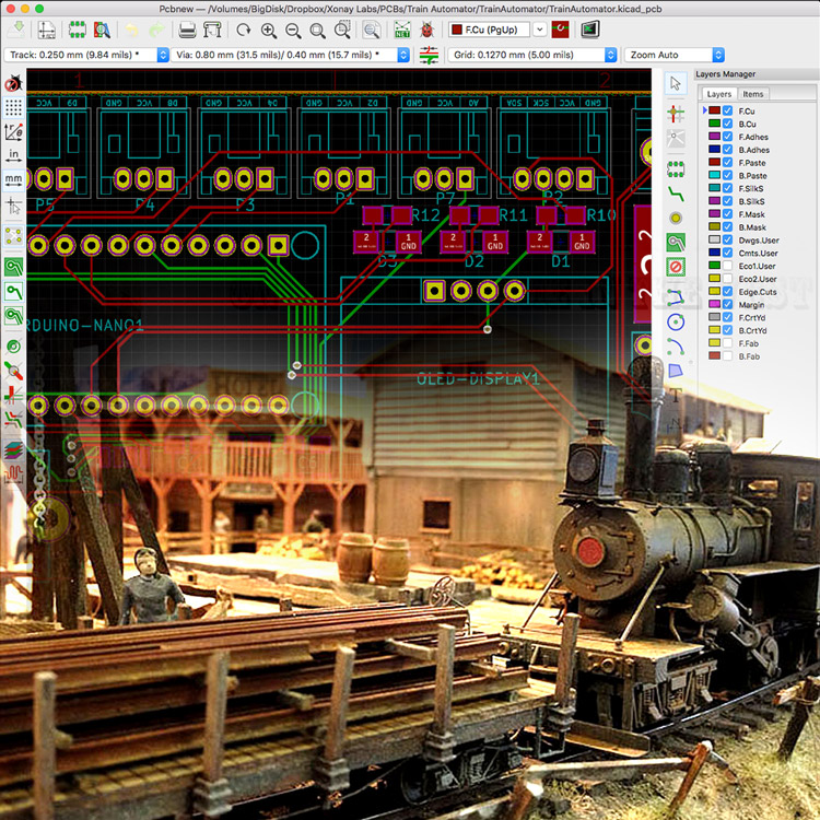
To get a rough idea on how I want to connected everything, I use KiCad to make a schematic diagram. The schematics aren’t very complex, but due to the number of items I want to connect, it does include a lot of connections. And since I want to debounce all the buttons and switches, I also need to throw in a hand full of resistors and capacitors.
The only “exotic” component of the activity board controller is a MCP23017. This is an I²C IO expander. The Arduino Nano I’m going to use doesn’t have enough in- and outputs to connect everything I want. So this easy to use IC is going to help me out.
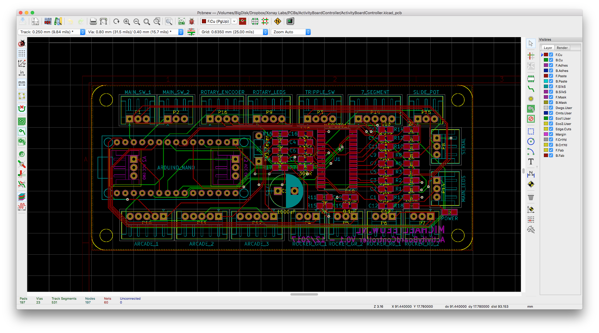
I initially planned to build the activity board controller with the help of some perfboard. But after I counted all the connections and components, I quickly decided that a 2 layer manufactured PCB would be a better choice. So, with the help of KiCad and a few cups of coffee, I managed to sketch up the layout above.
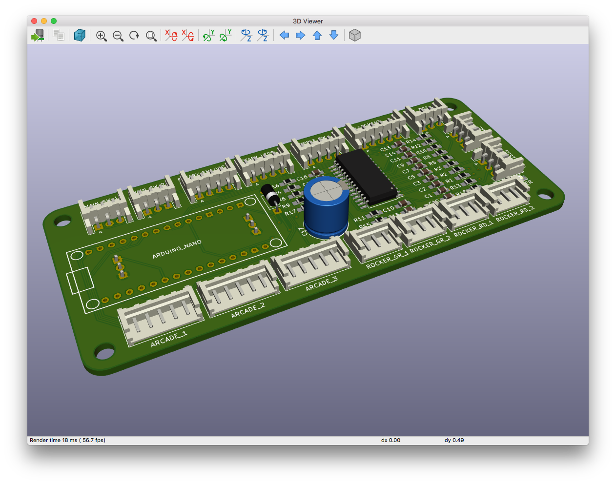
Once again, the KiCad render function helps me to visualize the end result. It sure as hell looks rather impressive for a self made kids toy.

So now the waiting begins. Luckily I recently discovered AllPCB. Extremely cheap prices with lightning fast delivery. (And no, this is not a sponsored post!) So within 5 days, the package above arrived on my doorstep for only $18,- Sweet!
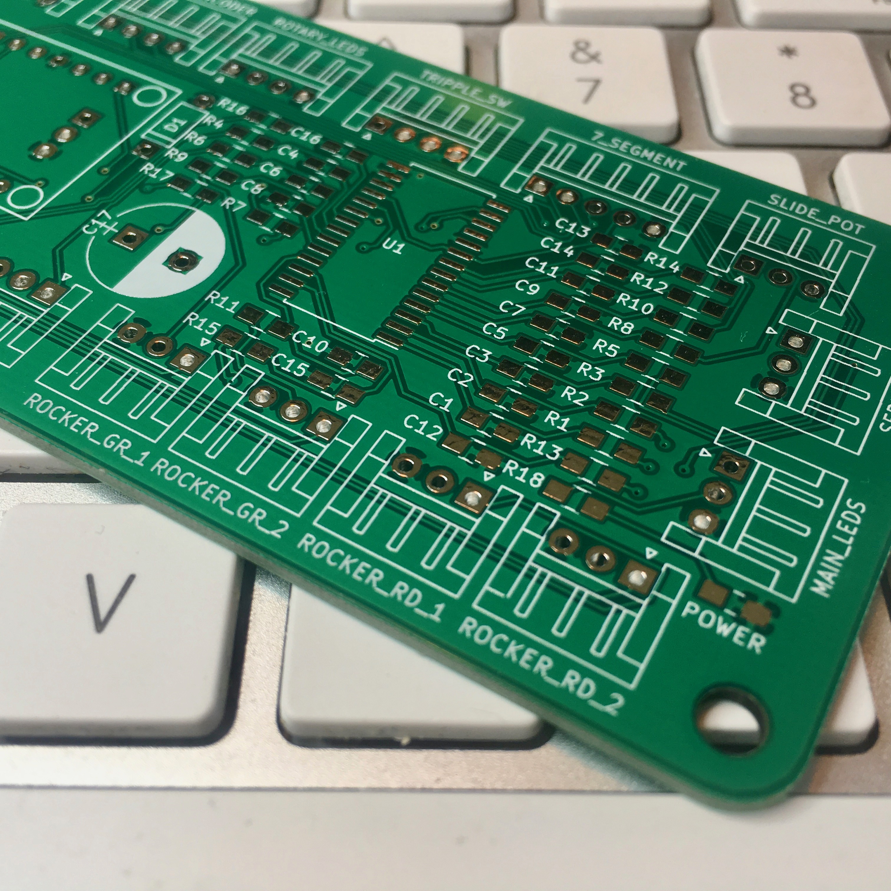
This is the beauty of hardware design: It’s so satisfying to physically hold your own design!
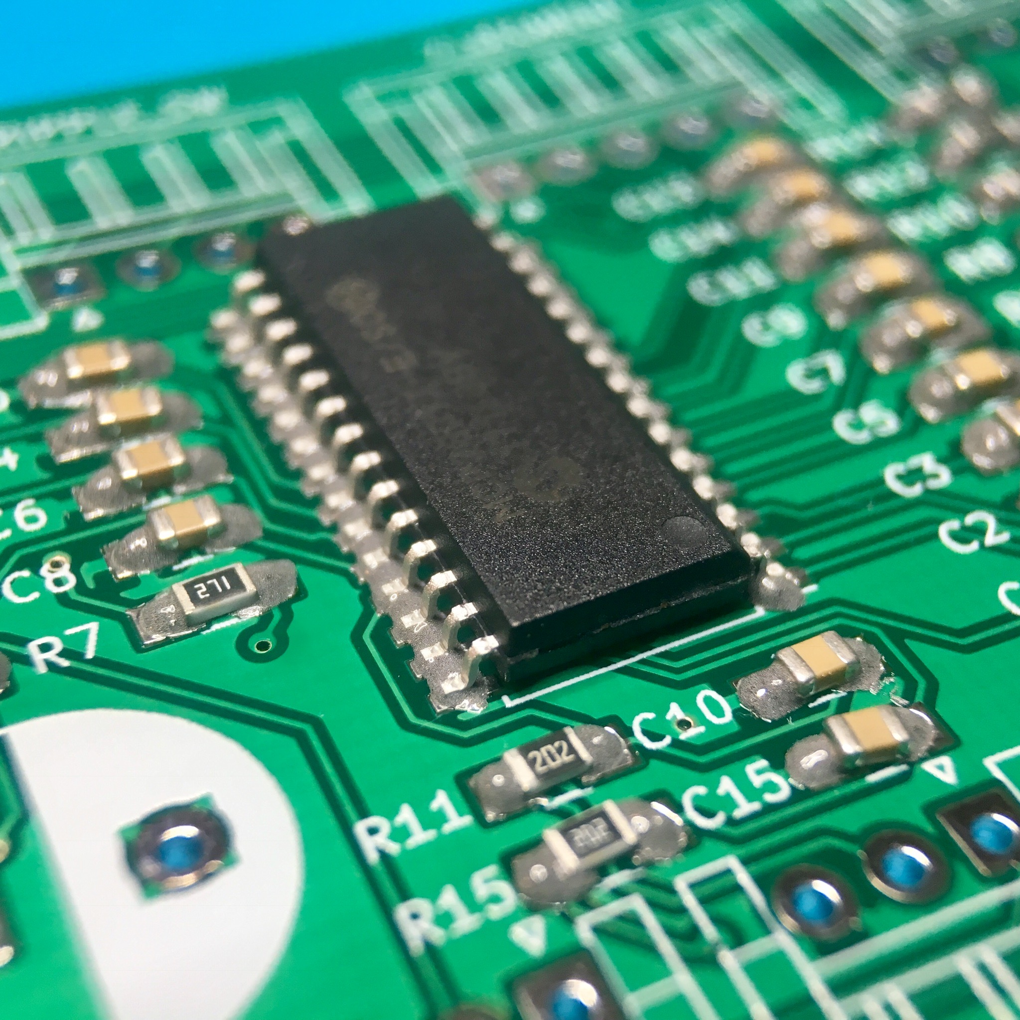
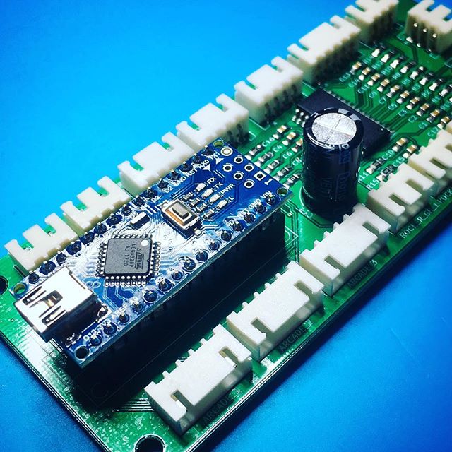
With the huge amount of 0805 SMD parts, I decided to put my hot air rework station to work. So after applying some solder paste by hand (I didn’t order a solder paste stencil), I use some tweezers and a lot of patience to put everything in place.
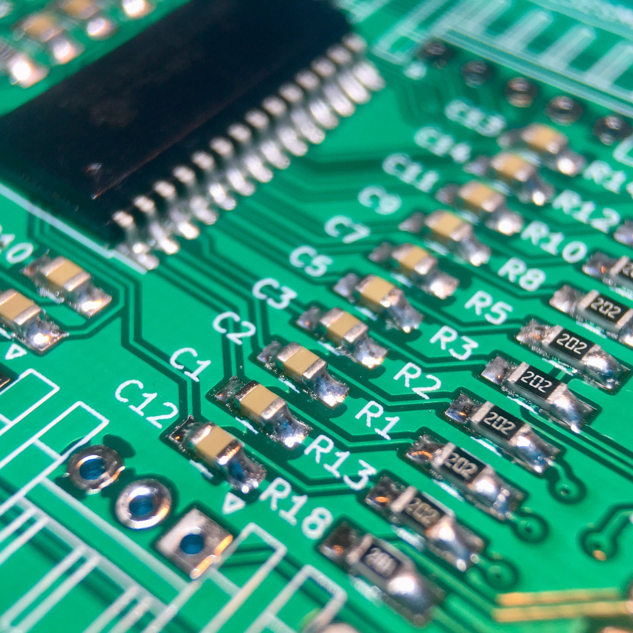
A little bit of heat later, everything is soldered in place.

The JST connectors, the Arduino and one big capacitor are soldered in place with my old fashioned TS100 soldering iron.
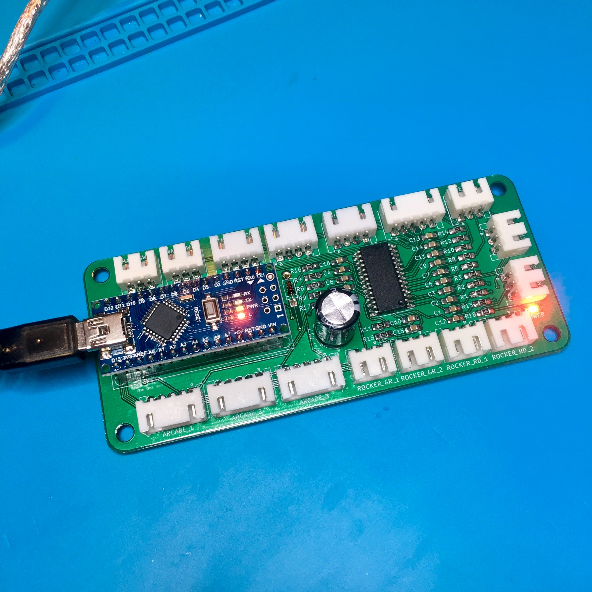
After connecting an USB cable to my Arduino, I’m relieved to say the power led did what it had to do. Time to mount the controller to the activity board.
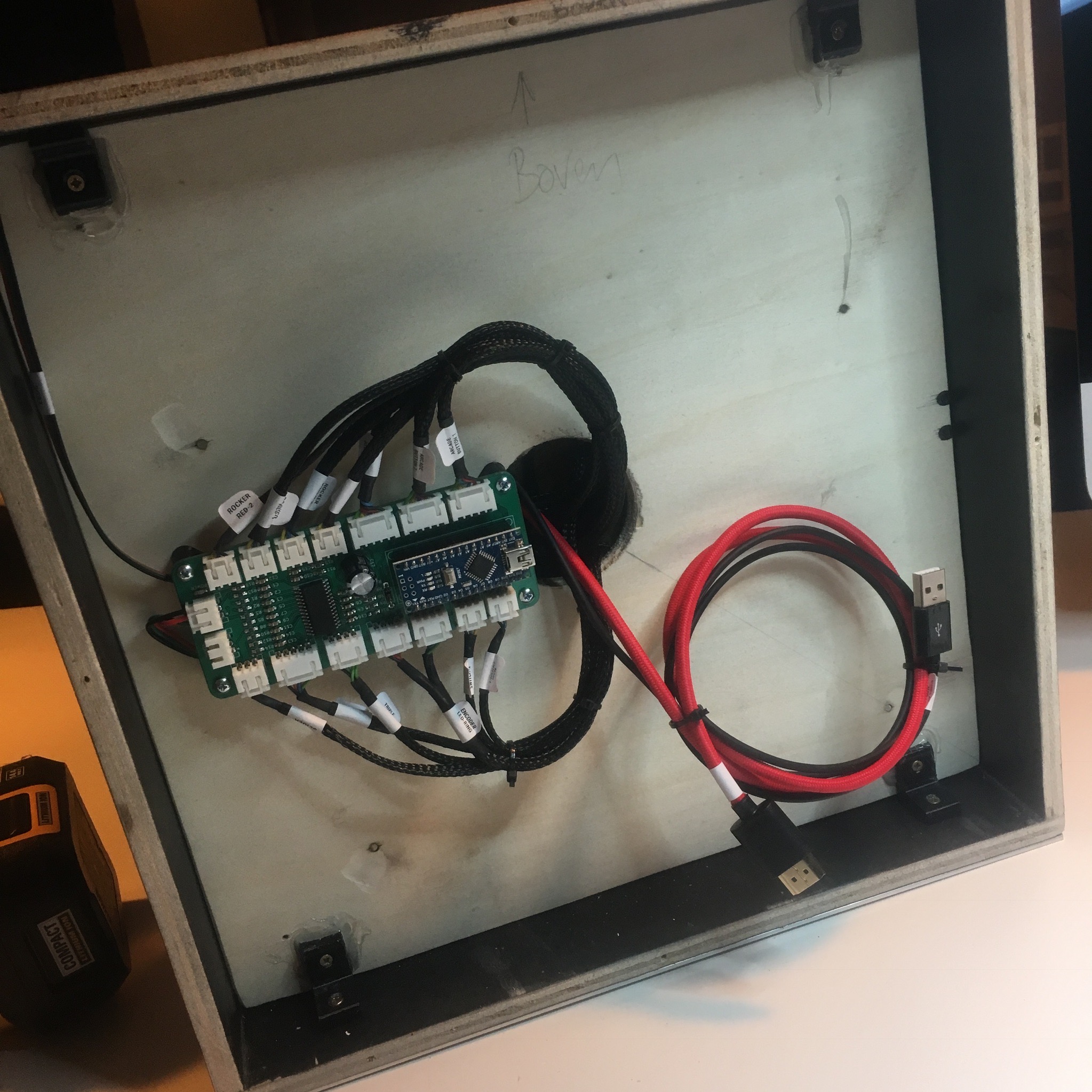
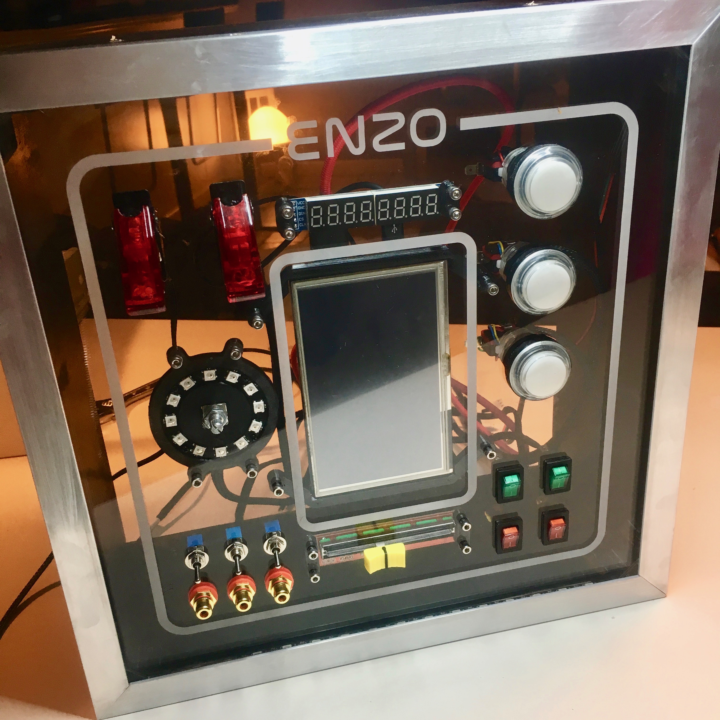
With the help of a 3D-printed spacer/mount, the activity board controller is held in place. And due to all the convenient JST-connectors, everything is connected within a few minutes.
Now, It’s the moment of truth. With the help of some rudimentary test code I can test if everything works as intended. The code helps me to test the following functions:
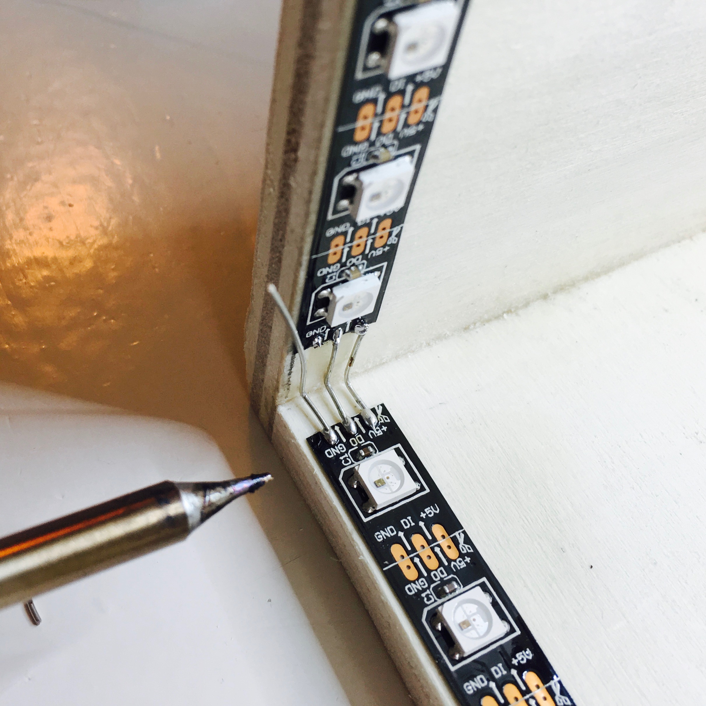
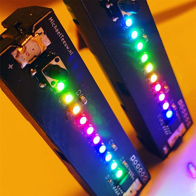
- Control the WS2812 LEDs.
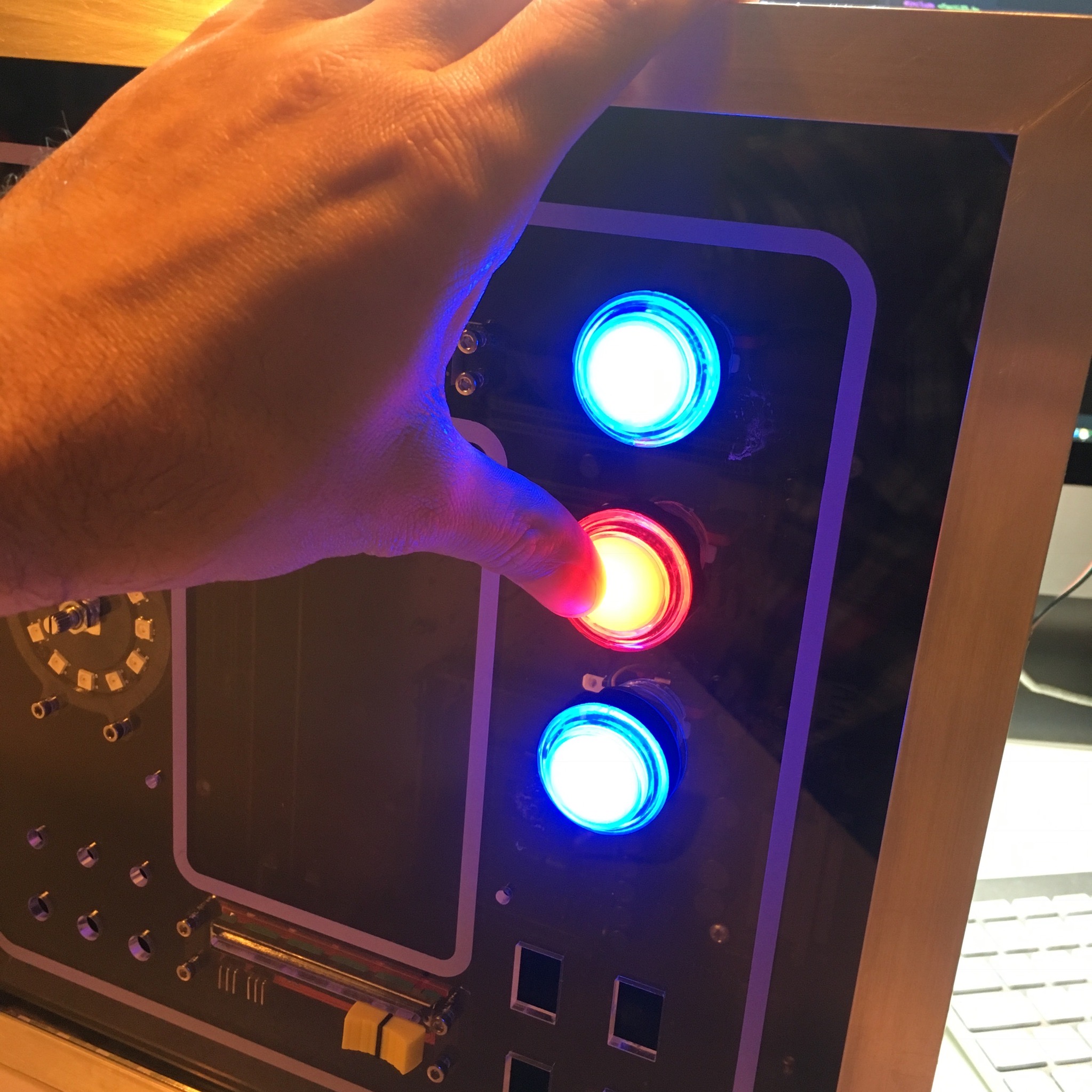
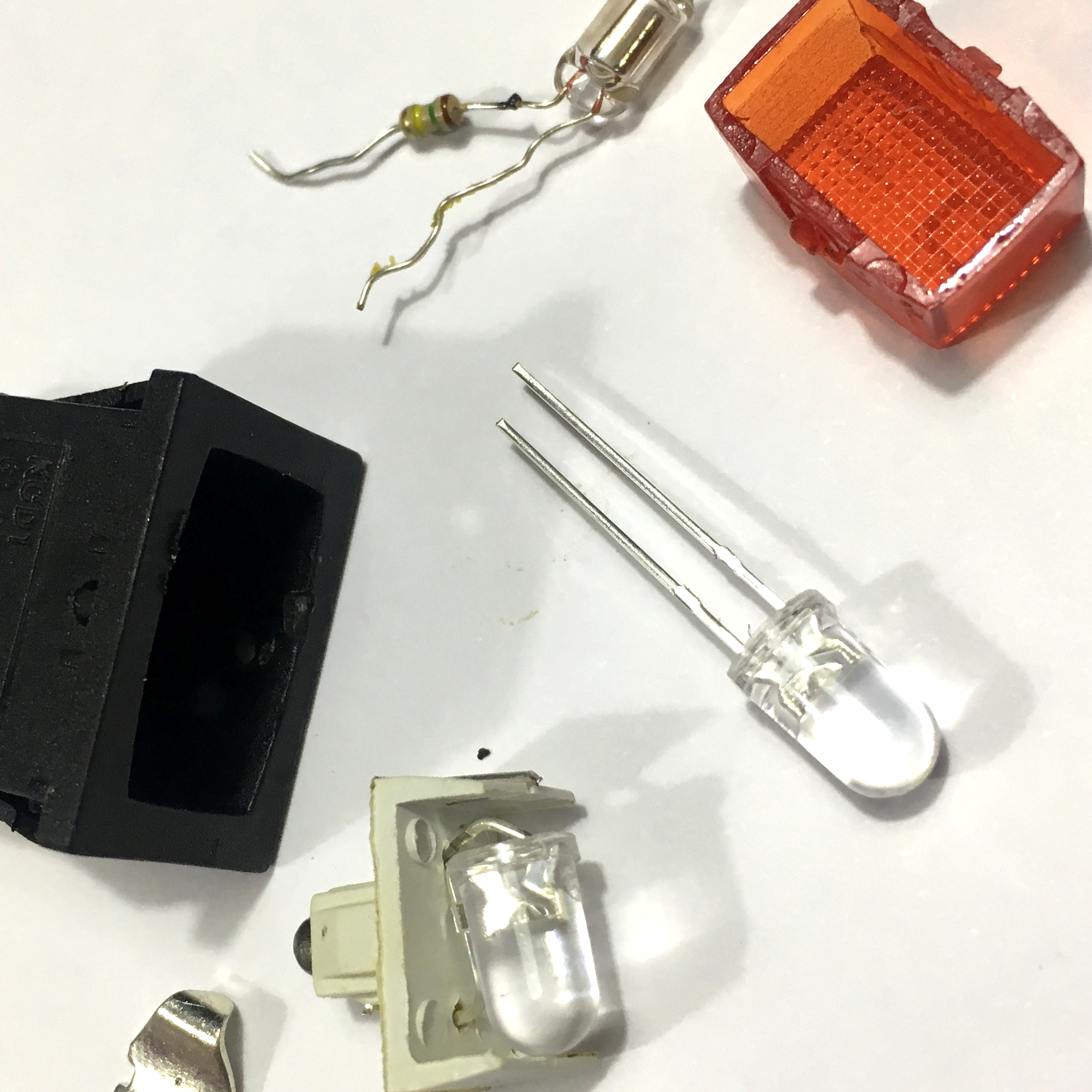
- Control the regular LEDs incorporated in the main switches and rockers.
- Read the input of the 13 buttons/switches and rotary controller.
- Control the MAX7219 7-segment display.
- Read the slide pot value.
And as you can see in the (not so beautifully filmed) video above, these functions work as intended. Awesome!
Next step? Work on some more advanced code.
Activity Board: It's all about the code!