As I’ve mentioned on my blog before, my dad is an avid model train hobbyist. This started way before I was born, so during my time as a kid living at my parents, I contributed to some of his projects. 20 years later, my contribution could use an update.
A lot of the items on his model track are brought to life using small motors, a lot of LEDs and some speakers. To control these items he uses relays triggered by a 555 timer. This way he (or visitors of the exhibitions in which he participates) can trigger these items with a press of a button. The 555 timers make sure the automated-items will run for a set period of seconds before going back to sleep.
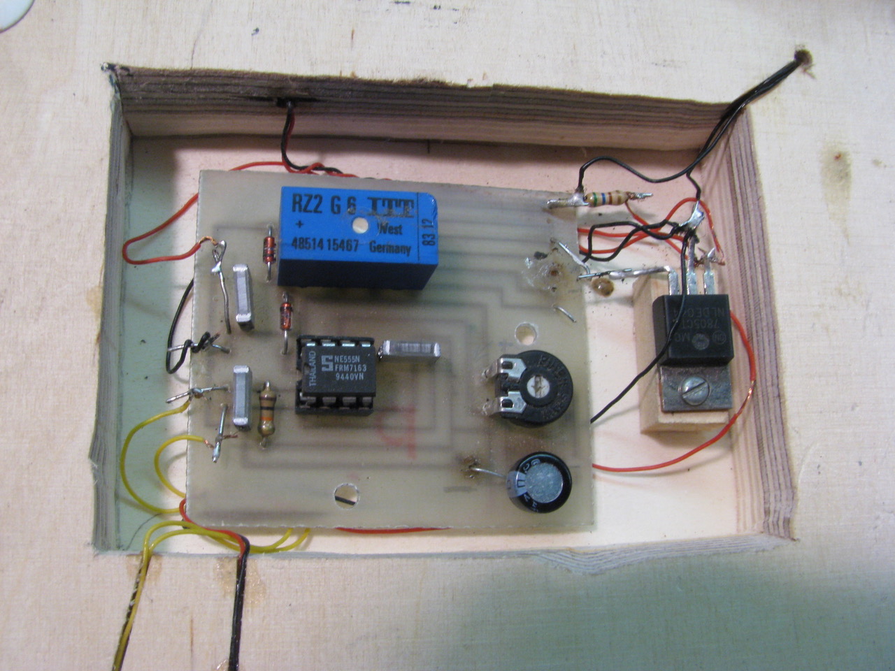
These timer circuits are all based on a PCB we designed exactly 20 years ago. I spent my after-school hours to design a ‘compact’ PCB while my dad used the most toxic chemicals thinkable to home-etch these boards.
Now, 20 years later, he ran out of these boards. And since I couldn’t stop talking about the wonderful chinese PCB manufacturers, this was the perfect time to go for an updated PCB. No home-etching required.
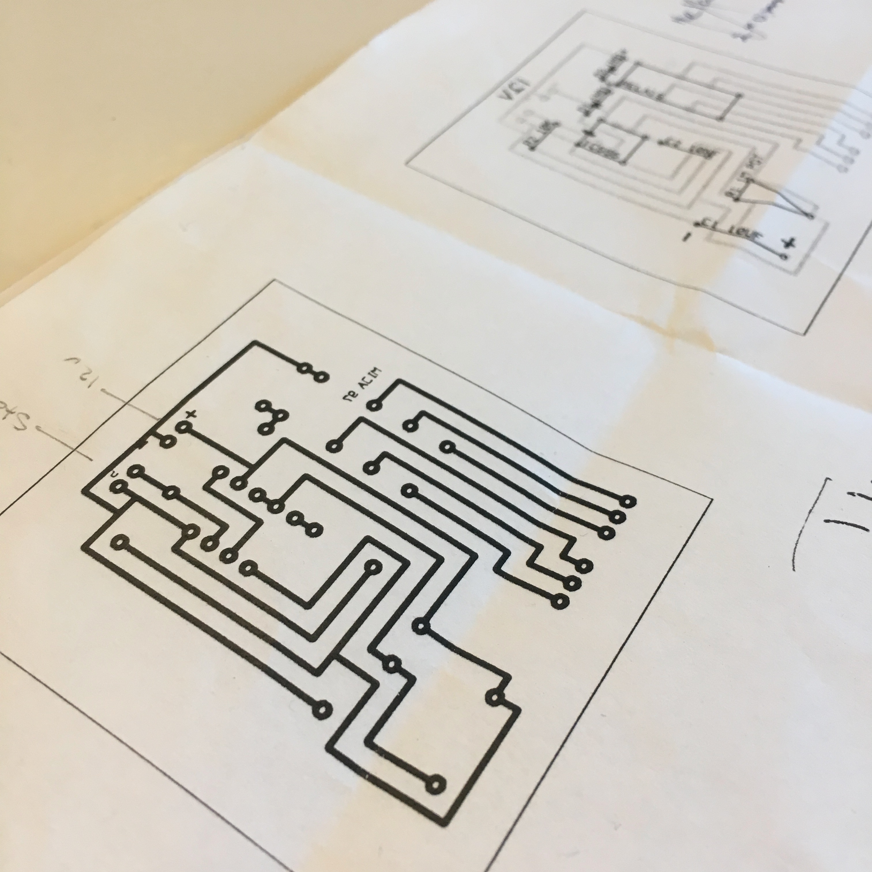
During the Christmas holiday my dad handed me the papers above. These were the original 20 year old printed schematics. As you can see the print has a mirrored text stating “MIJA 97”. MIJA (Michael & Jaap) is the name we used for our colaboration projects. The fact that 1997 was exactly 20 years ago, made this project much more special.
My dad had a few requirements:
- Powered by 12V.
- To keep things simple: no exotic parts. So it must be a real 555, and not a micro controller.
- Use trough hole components. My eyes and hand coordination are much better than his. (Although he’ll probably tell you it’s because he only has trough hole components in stock.)
- Write the component values on the PCB, so no additional documentation is necessary.
- Make it compact, but easy to solder and to connect.
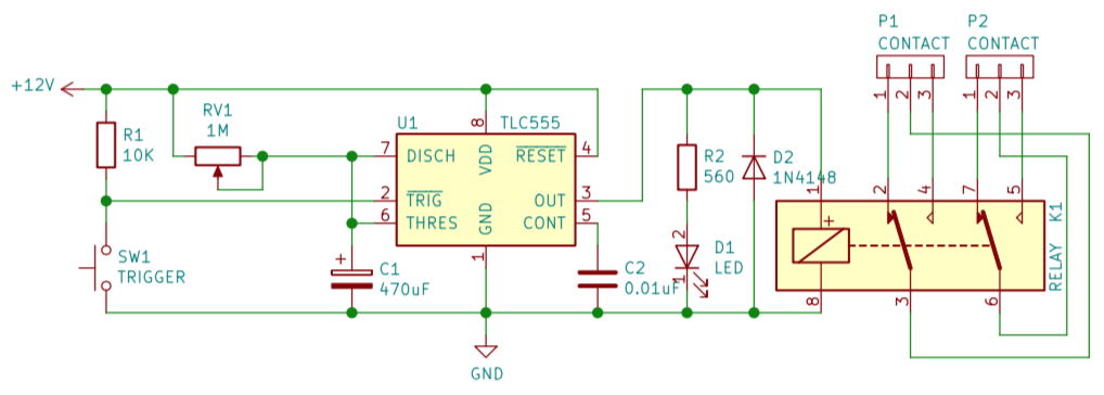
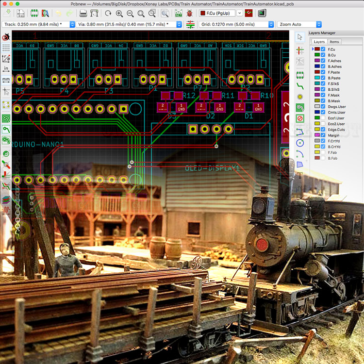
So right after the Christmas dinner, I jumped behind my laptop and started drawing the above schematics using KiCad. The design was mostly based on the great article by Electronics Tutorials. But I did decide to live on the edge by letting the 555 timer control the relay without the use of a transistor. The relay we were using only draws ~30mA, and the previous boards managed to survive for 20 years. I figured this was probably a safe bet.
Next up was the design of the PCB. This was the part in which I could show my dad we made great progression in the past 20 years. Of course I would have preferred to use SMD to make the PCB ridiculously small, but with a total size of 30mm x 40mm it ended up being a nice and compact PCB anyway.
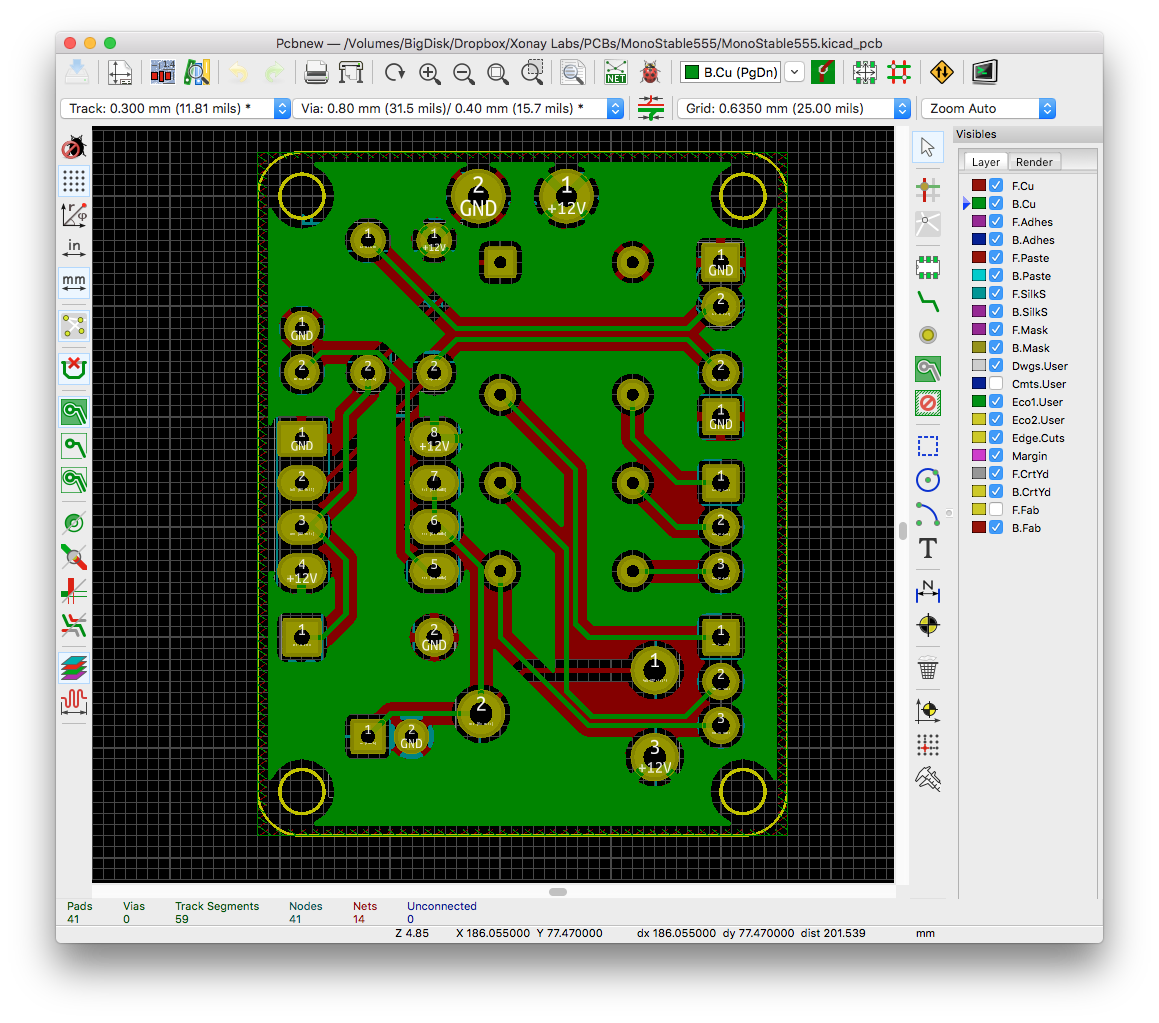
The PCB could have been a simple one layer PCB. But since 2 layer PCBs are just as cheap, I had to opportunity to take an easy shortcut every now and then.
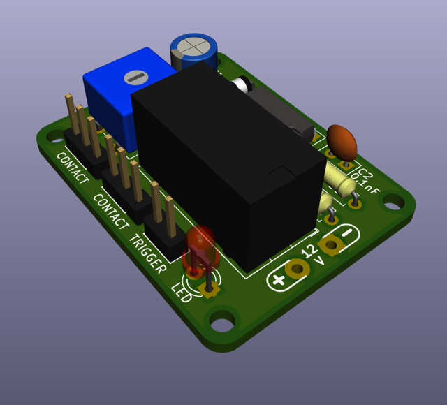
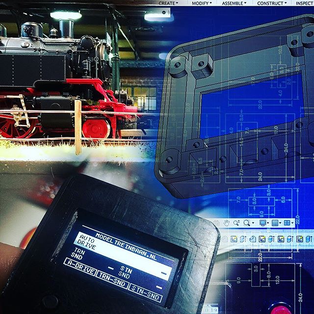
The awesome 3D render feature of KiCad really helps to visualize your PCB.
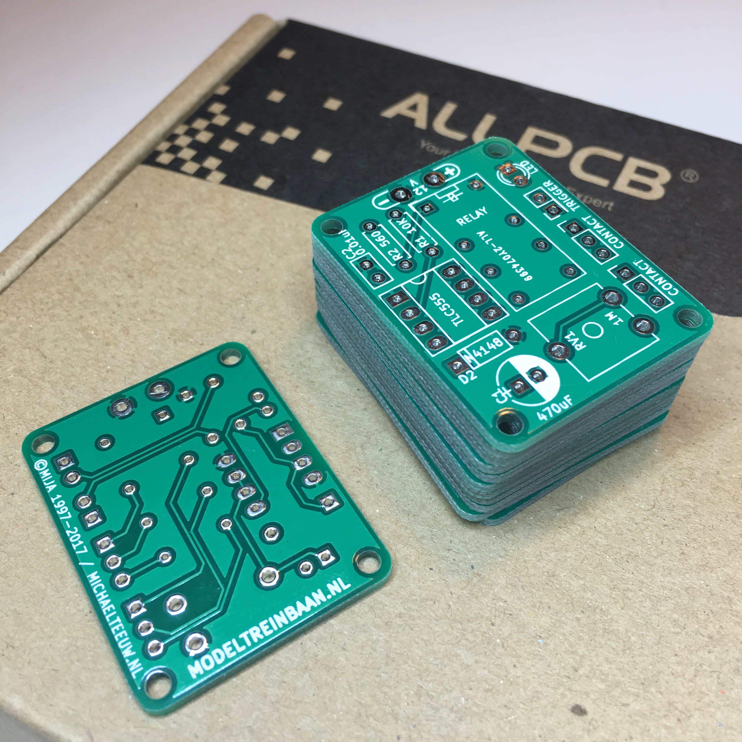
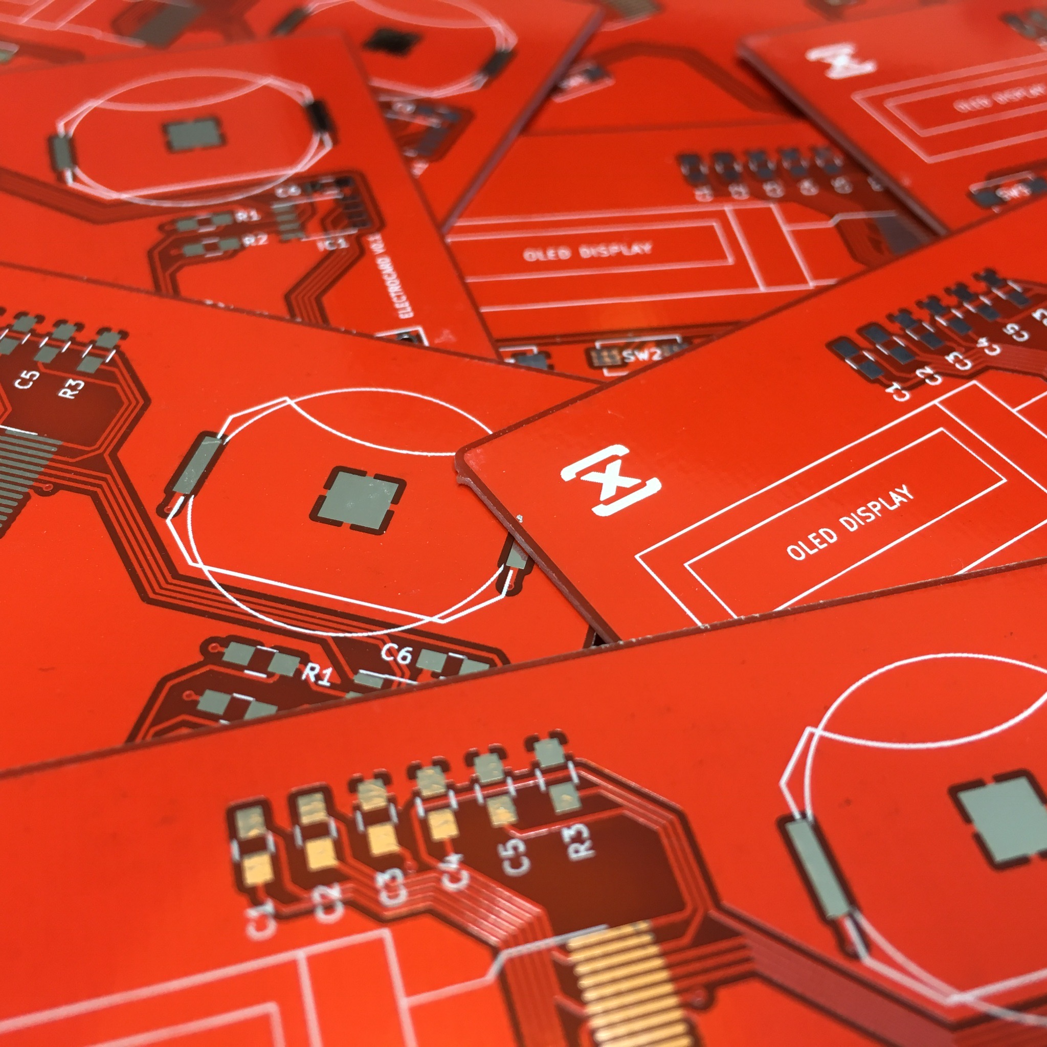
This project was the perfect project to try out AllPCB.com. Not only do they offer extremely low price PCBs. In most cases it also includes TNT or DHL shipping. In this case I paid $10,- for 10 PCBs including shipping. Withing 5 days after my dad asked me to make the new PCBs I received a well packed shipment with high quality PCBs. I was blown away.
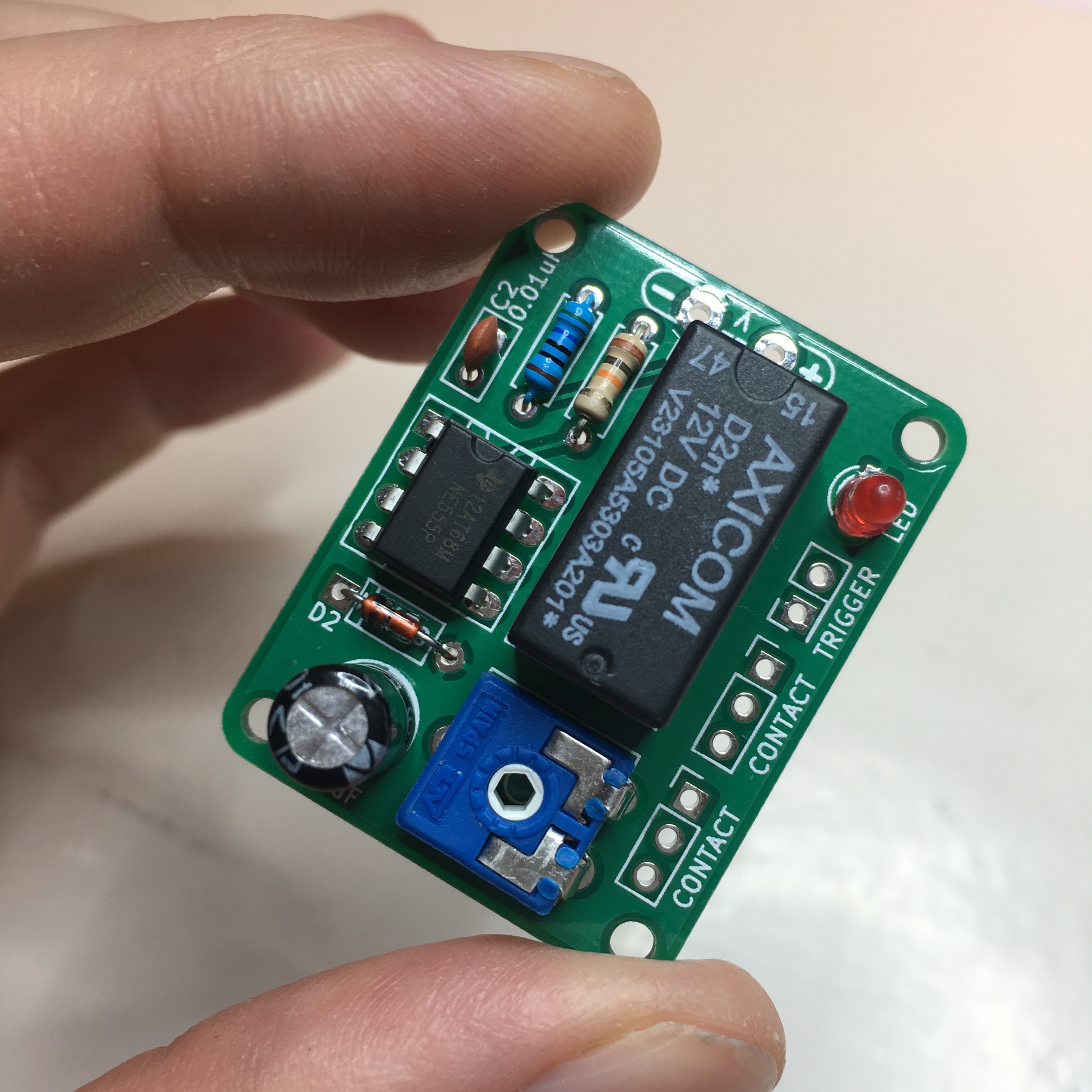
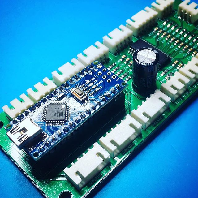
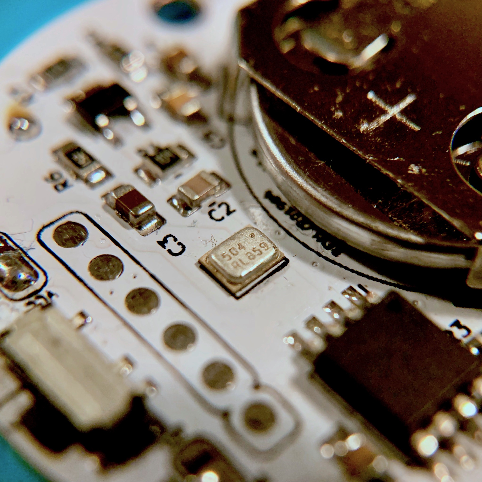
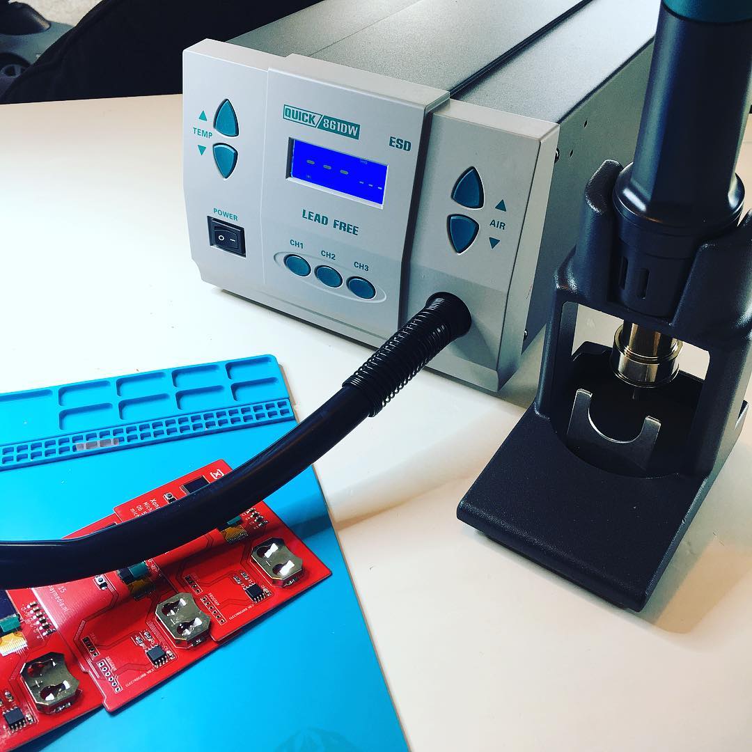
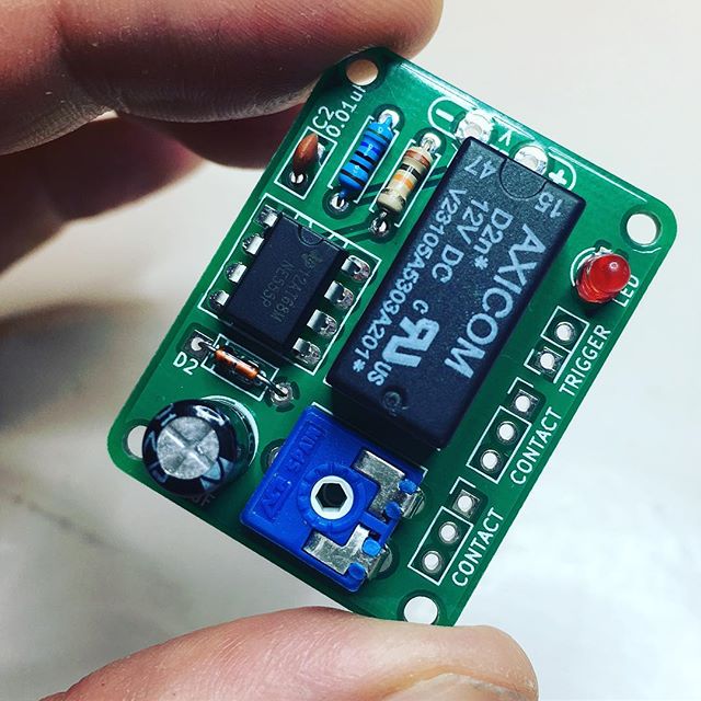
Of course I couldn’t wait to add all the components and see the end result. It only needed some solder and heat to complete the first unit.
And with those final ingredients, I had an awesome new years gift for my dad!
If you want to build these yourself, check out the 555 Mono Stable Relay GitHub repository including the KiCad files. If you just want to order the PCBs, simply download the GERBERS.zip and upload these to AllPCB.com or any other PCB manufacturing service. If you need to enter the dimensions, 30mm x 40mm will work.
Enjoy the soldering!