To improve my robot arm’s accuracy, I wanted to add an absolute position feedback mechanism. Aside from it’s accuracy, it would also prevent the need for end stops. But most importantly, it would give me a reason to play with a AS5600 12-bit on-axis magnetic rotary position sensor.
Robotic Arm: Pulley & Belt Transmission
With the AS5600 I’m able to get 12 bit information about the joint’s current position. This means I have an accuracy of 4096 steps. Because the AS5600 is able to configure a start and stop position, these 4096 steps can be measured within a custom defined range of motion.
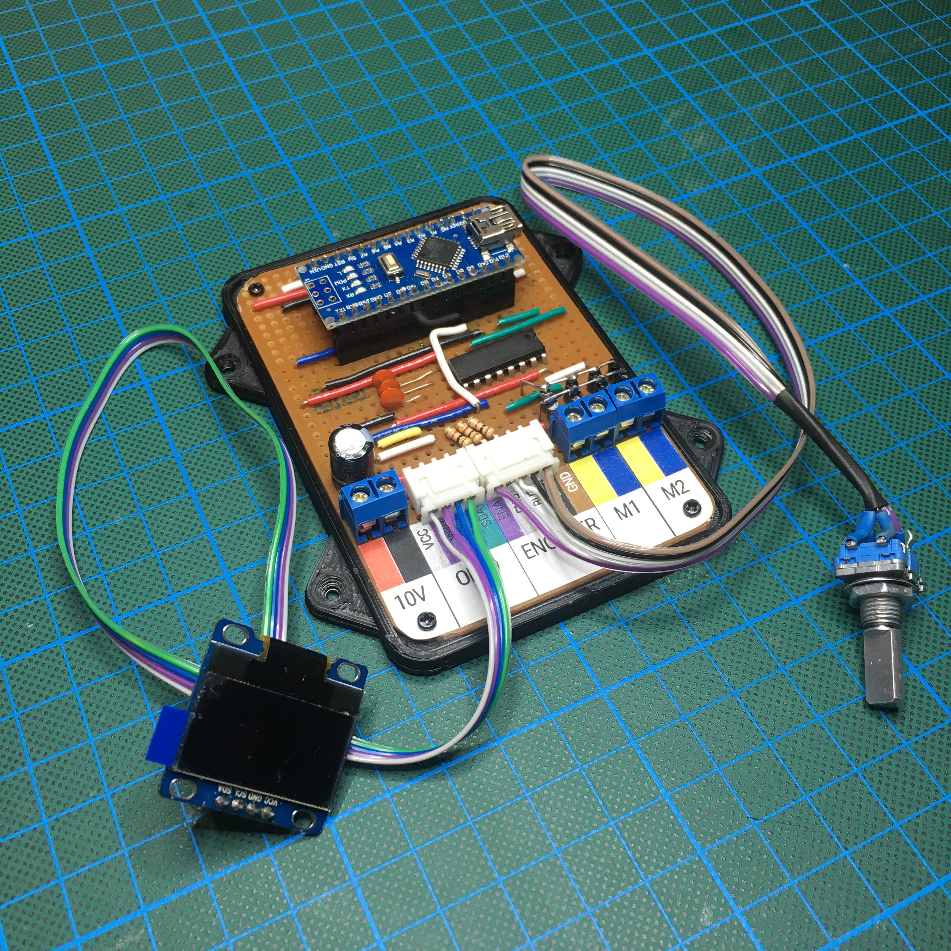
The AS5600 uses I²C communication, and therefor I needed to add 4 wires to the convenient breakout board I bought on eBay: VCC (it supports both 5v and 3v3), GND, SDA (Data) and SCL (Clock).

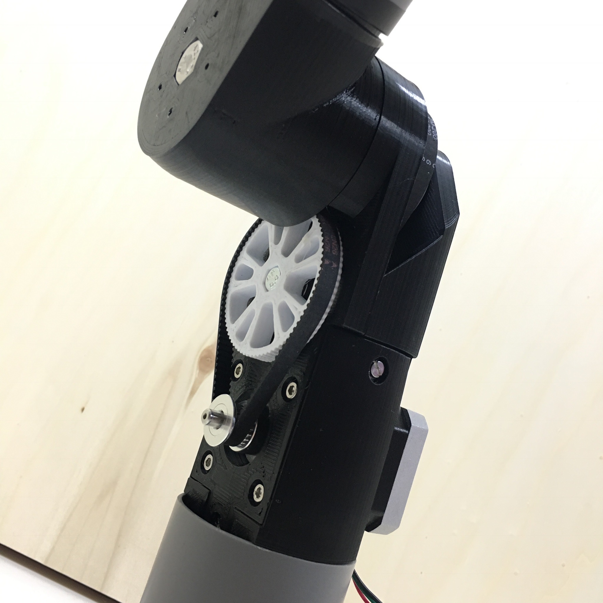
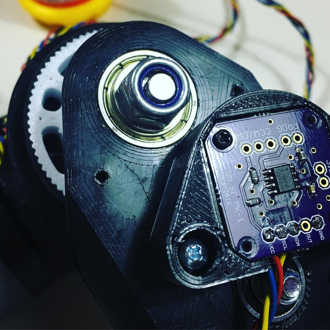
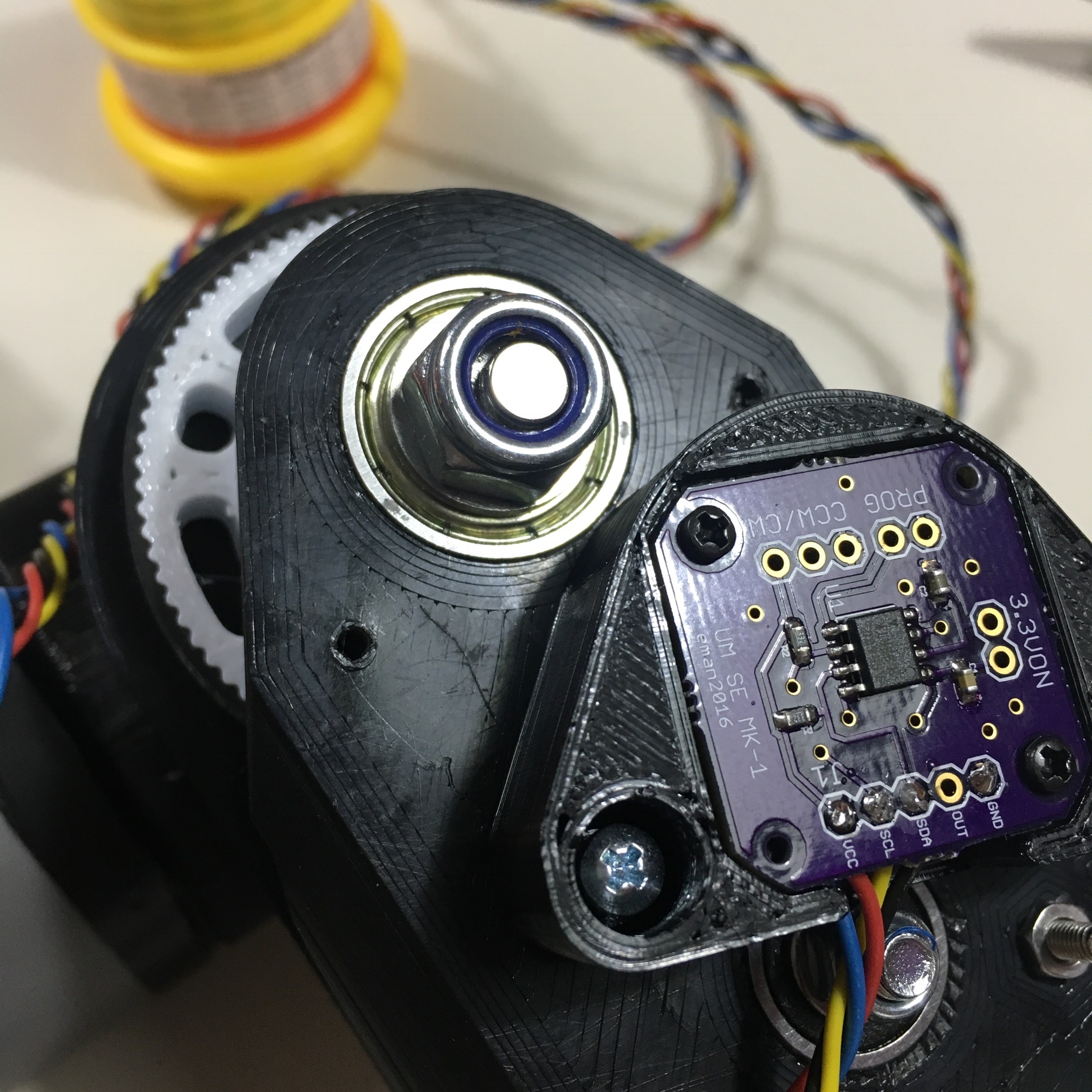
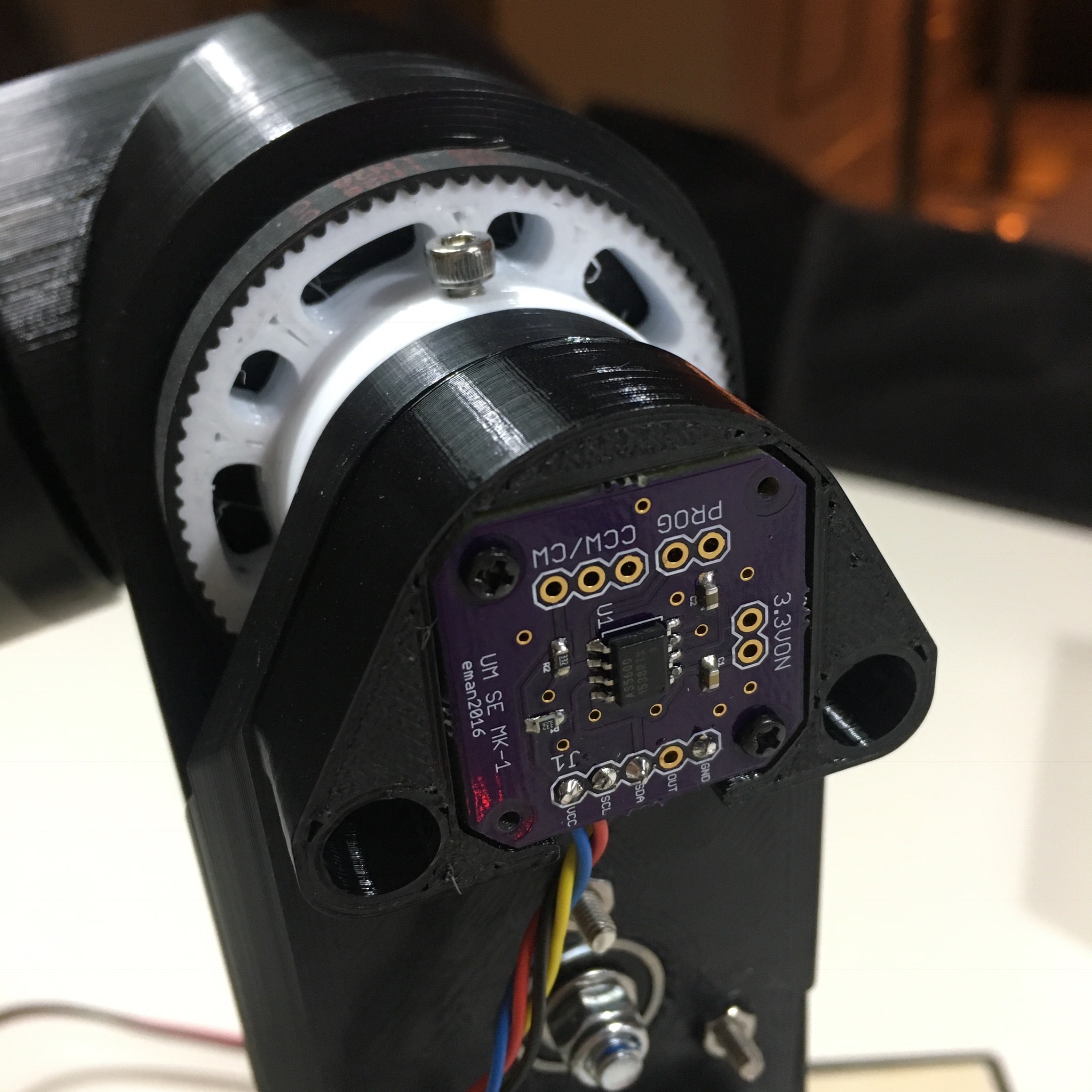
After adding the wires, it’s time to mount it onto the joint. Since the AS5600 IC needs to be positioned above the main shaft of the joint, I 3D-printed a mount to easily mount it on the correct position.

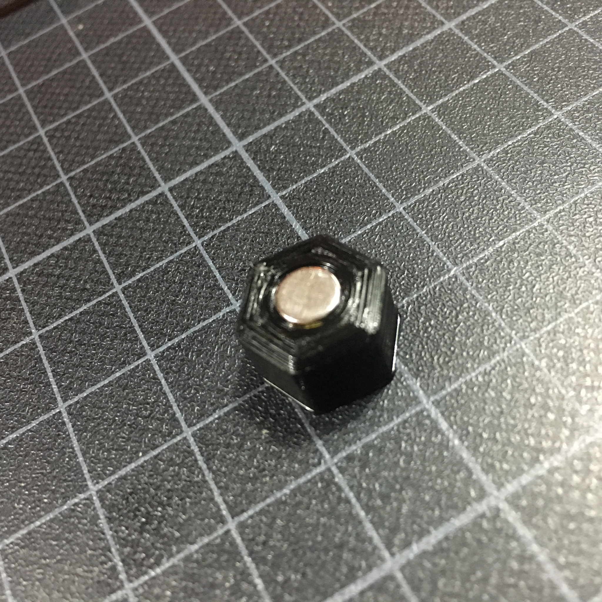
Because the AS5600 does it’s measurements based on a magnetic field, a small neodymium magnet is mounted onto the shaft.
To improve the sensor’s reading, it’s recommended to mount the magnet in the exact center of the shaft. A simple 3D-printed hex nut with magnet slot makes this easy as π … as pie.
With the magnet in place, it’s time to screw the sensor onto the joint.
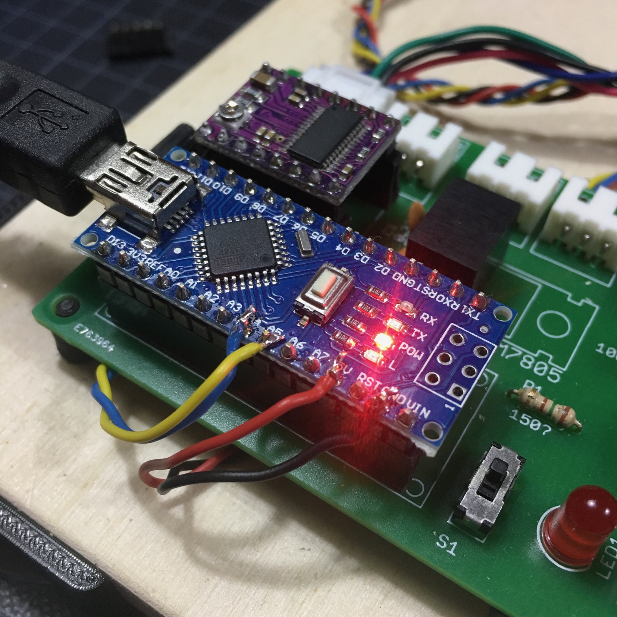
Of course, the controller board i’m currently using for testing hasn’t got the necessary connections for this sensor. But that’s nothing I can’t solve with my hot and steamy soldering iron.
To use I²C on an Arduino Nano, you need to use pins A4 and A5. The necessary power is also provided by the Arduino.
With all the hardware in place, it’s time for some coding. The creators of the AS5600, AMS, are awesome enough to share some example code, making it pretty convenient to use the sensor within an Arduino project. Check out the example project here.
And with the provided library, it’s pretty easy to read out the sensor:
#include <Arduino.h>
#include <Wire.h>           // Support for I2C encoder
#include <AMS_5600.h>       // Available via the AMS website:
                            // http://ams.com/eng/content/view/download/381996

// Create a sensor instance.
AMS_5600 ams;

void setup() {
    // Start I2C.
    Wire.begin();

    // Start the serial Connection.
    Serial.begin(9600);
}

void loop() {
    // Retrieve the angle from the sensor.
    word angle = ams.getRawAngle();

    // Print the angle to the serial buffer.
    Serial.println(angle);

   delay(50);
}
As you can see in the following video, this works pretty well. (I used the Arduino IDE’s plotter to show the data as a graph.)
So we’re good to go, right? Wrong! It turns out I²C isn’t fast enough to be used in sync with the motor running smoothly. This means I could only read out the data from the sensor while the motor is stopped. Which defeats the whole purpose of the sensor!

Of course I could spend days trying to solve this. I could try out other types of encoders. But honestly, It isn’t really important. I don’t expect my robot arm to perform an open heart surgery anyway. So for now I just take for granted what I’ve learned about the AS5600 and continue with the project without a feedback sensor.
If you have any ideas for a good solution, let me know in the comments down below!
Next up, the joint covers! And of course, a nice solution for the end stops … which do need to be implemented now.