With the first final motor unit assembled, and the newly gathered knowledge about Eagle PCB it is time to work on the motor control unit.
Automatic Curtains: Assembling the motor units.
Since I already have a prototype of the motor control unit, designing the schematics of the new version isn’t all that difficult. But since I’m making an professional circuit board anyway, I took the opportunity to add some small extra features.
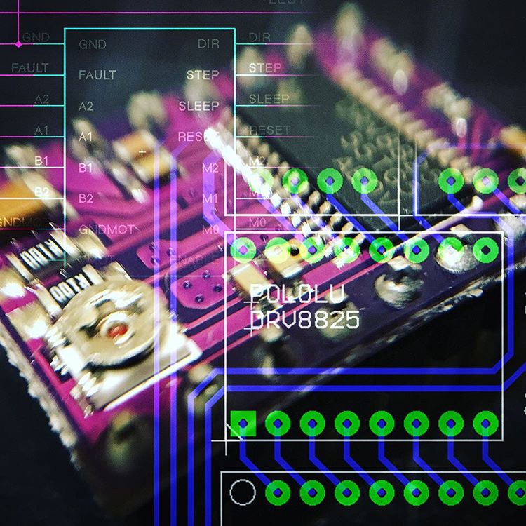
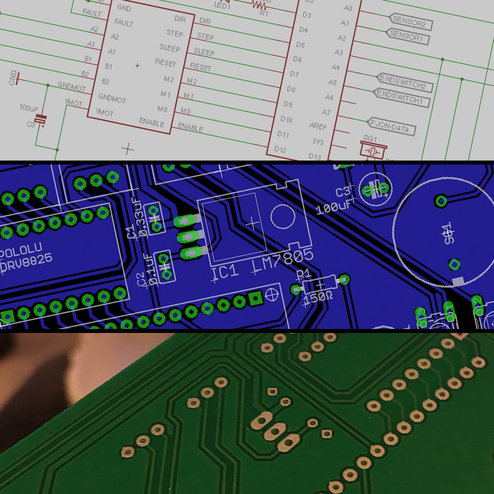
The circuit above contains two important elements: the pololu DRV8825 stepper driver on the right, and the Arduino Nano on the left. In addition to this, there are a few extra parts we’ll go over:
- LED1: This LED will allow me to give me debug feedback without any serial connection. For example: if the LED blinks once, the motor unit is calibrating. If it blinks twice, there are issues with the data connection.
- R1: The is the 150 Ohm current limiting resistor for LED1.
- IC1: This LM7805 Linear voltage regulator regulates the 5 volt necessary for the Arduino. Of course, the Arduino has a built in regulator, but since the stepper motor occasionally adds some voltage spikes, this is an easy solution. Especially since this voltage regulator allows input voltages up to 35 volts.
- C1 & C2: These capacitors support the voltage regulator in it’s difficult duty to generate a steady voltage for the Arduino.
- C3: The Pololu DRV8825 carrier board uses low-ESR ceramic capacitors, which makes it susceptible to destructive LC voltage spikes. One way to protect the driver from such spikes is to put a large (at least 47 µF) electrolytic capacitor across motor power (VMOT) and ground somewhere close to the board. I opted to go for an 100uF capacitor.
- S1: This switch allows me to toggle the 5 volts which powers the Arduino. If I want to power the Arduino using USB (while programming or debugging), I can simply toggle this switch.
- S2 & S3: These switches allow me to control the curtain on the board. Although I also add a connector for external switches, these onboard switches will come in handy during testing.
- SG1: A piezo buzzer is added to the board for additional feedback. This buzzer will probably only be used for critical situations (i.e. when the stepper driver reports a fault using the fault line).
In addition to the on-board parts, the board will contain connectors for the motor, the end switches, the control buttons, additional sensors (for example: a sensor to check if the door behind the curtain is open) and the power (12v) and data.
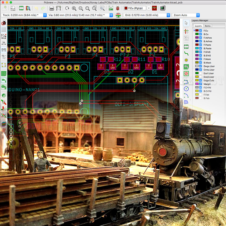
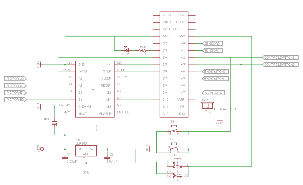
With the schematics in place, it is time to design the board …
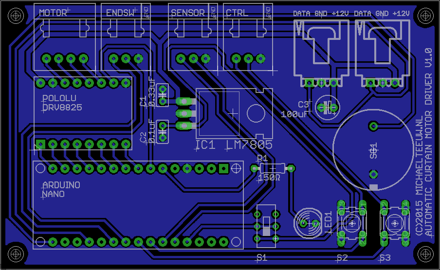
Somehow, it always satisfies me when I manage to design all the routes on one layer without jumper wires and without the use of auto routing. I spend a lot of time to not only get everything in place, but also to make to board look appealing.
As you can see, I’ve added two power & data connectors in paralel. This way I can daisy-chain my motor control units.
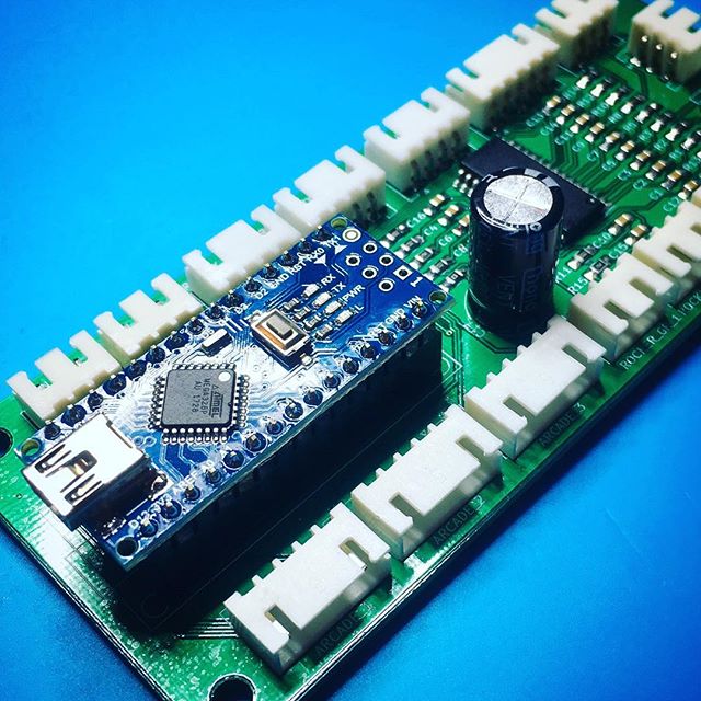
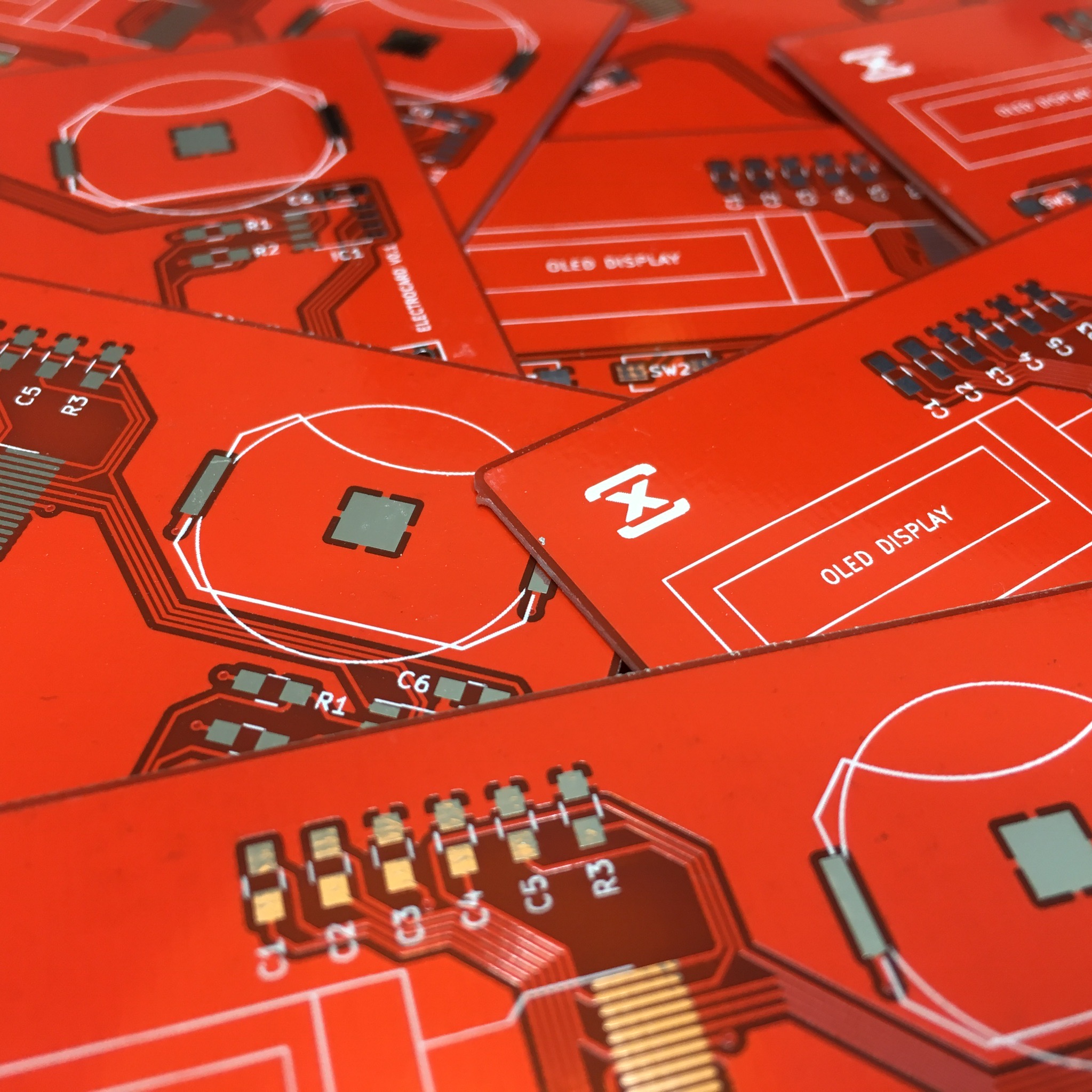
After finishing the board design an a small prayer, I ordered the PCB’s for my motor units. Luckily, Eurocircuits.be didn’t keep me waiting for too long. So exactly a week later, these beauties landed on my doormat.
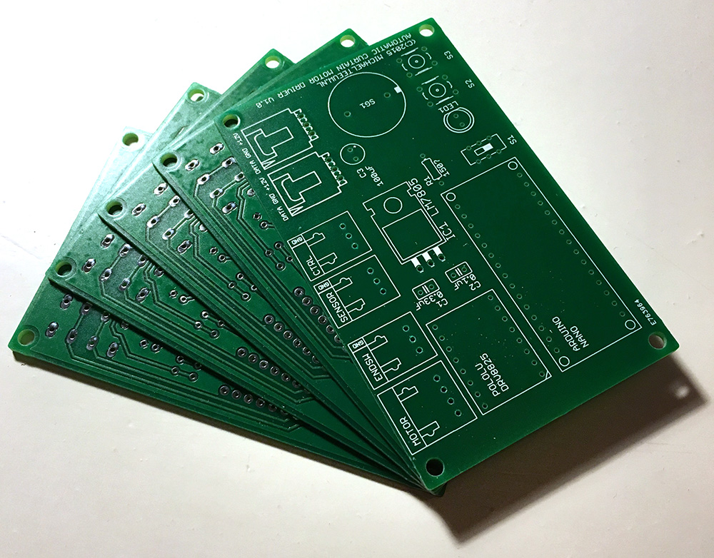
Even though I like the quality of the print’s. There were two minor issues:
- Since I ordered my board as a single layer board, it didn’t have plated through holes like my annoying dishwasher boards had. It turns out plated through holes are less like to delaminate.
- The drill size I used for the connectors were too small. The JST connectors didn’t fit! Whoops!
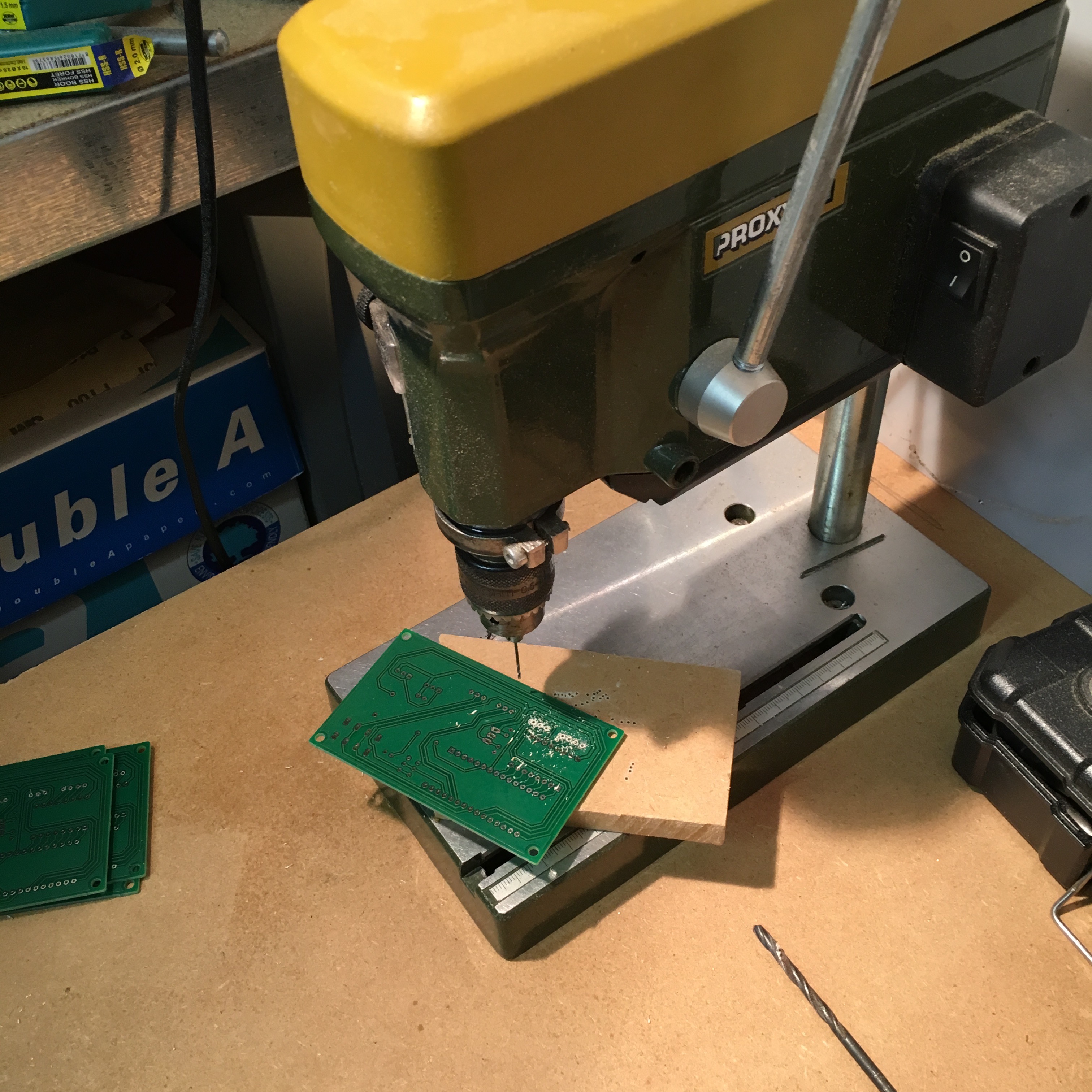
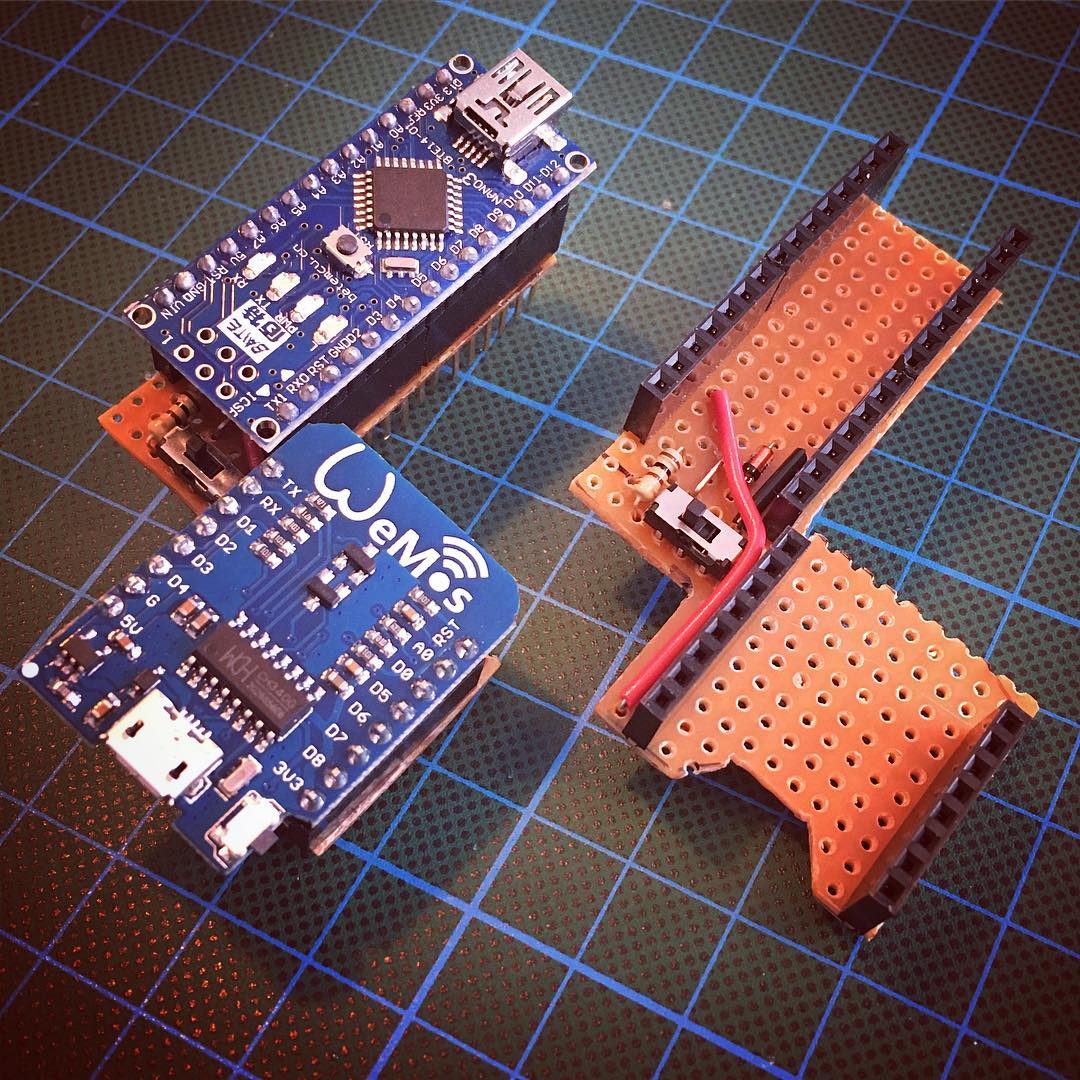
Luckily this second issue could easily be solved with the help of my Proxxon drill press and a 1 mm drill bit. Since I will be placing the Arduino and Pololu driver on female headers, It wasn’t necessary to drill out these holes as well.
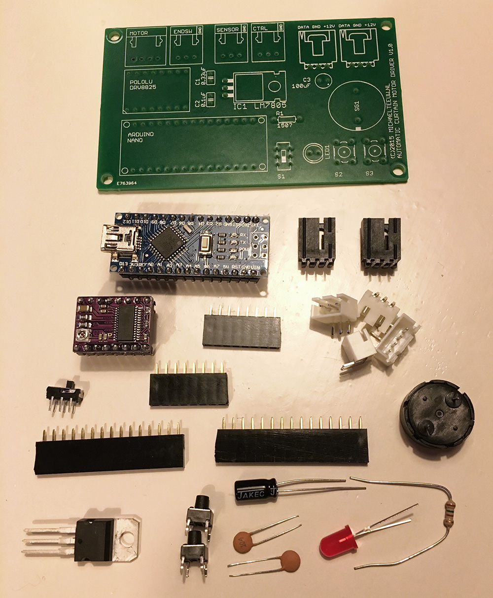
With all the holes in the right size, it was time to gather the parts …
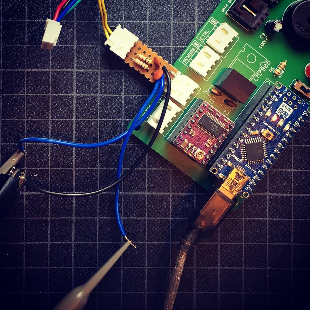
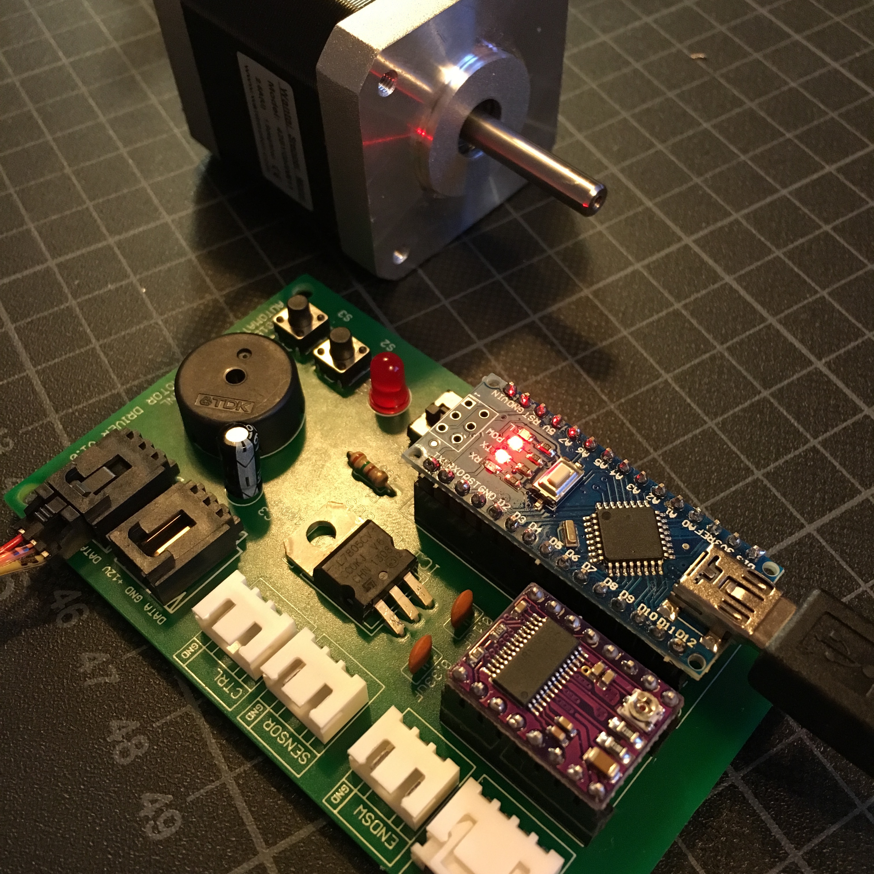
And start soldering …
And with the beautifully completed board, I could start testing the board.
And that’s where I discovered I goofed up. During the design of the board, I did create the Pololu part myself. Unfortunately, I was too lazy to design the Arduino part as well, so I used an online available drawing. It turns out, in the part I downloaded, the analog pins of the Arduino were in the wrong order. Resulting in a complete pin mixup. Because of this, the sensor connector is now connected to pin A6 and A7, which don’t support digital input. Luckily, this isn’t a deal breaker. I wont be using these sensor pins anytime soon, and If I do I can just use them as analog input.
So, let this be a good lesson for us both: make your own components, or if you download them: make sure to check if the pin connections are correct!
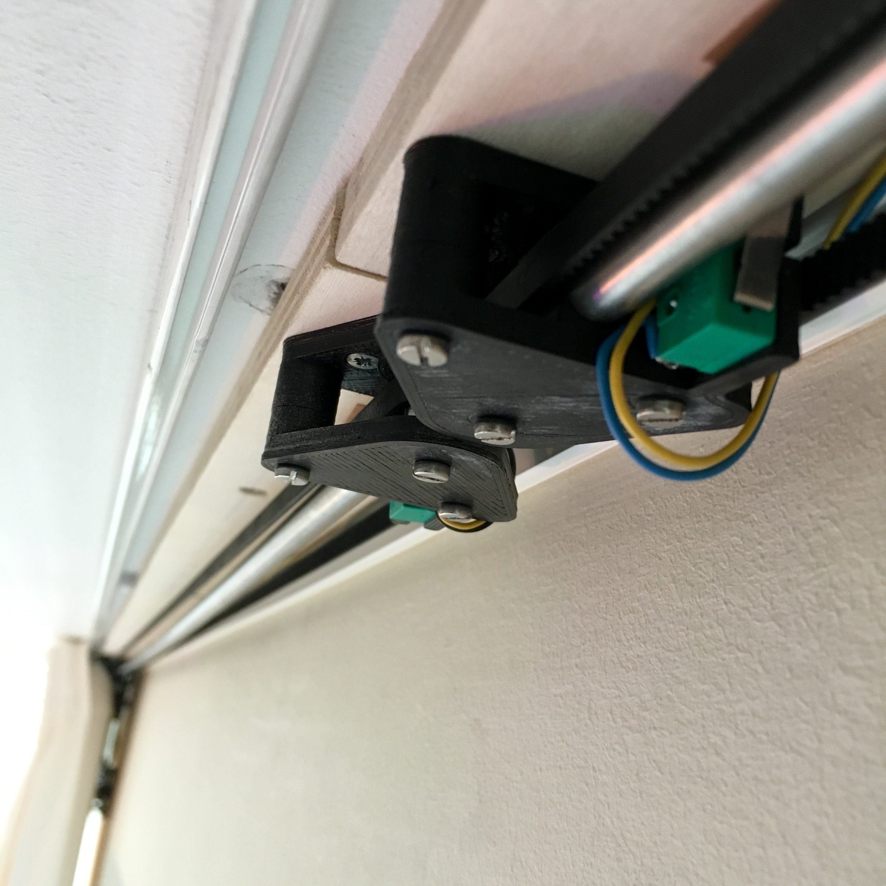
Next step? Mounting this first final set in place.
Questions or suggestions? Leave a comment down below!
Automatic Curtains: Designing a PCB Mount in Fusion 360 [Video]